Lens holder and method of use

A technology of holder and lens, applied in the direction of instruments, lenses, applications, etc., can solve problems such as difficulties

Active Publication Date: 2017-08-29
ESSILOR INT CIE GEN DOPTIQUE
View PDF4 Cites 0 Cited by
  • Summary
  • Abstract
  • Description
  • Claims
  • Application Information

AI Technical Summary

Problems solved by technology

[0003] Pad printing methods can present difficulties in consistently and accurately positioning the lens relative to the frame when placing markings (such as stamps or engravings) at the desired location on the lens, especially tinted or polarized lenses

Method used


Image

  • Lens holder and method of use
  • Lens holder and method of use
  • Lens holder and method of use

Examples


Embodiment Construction

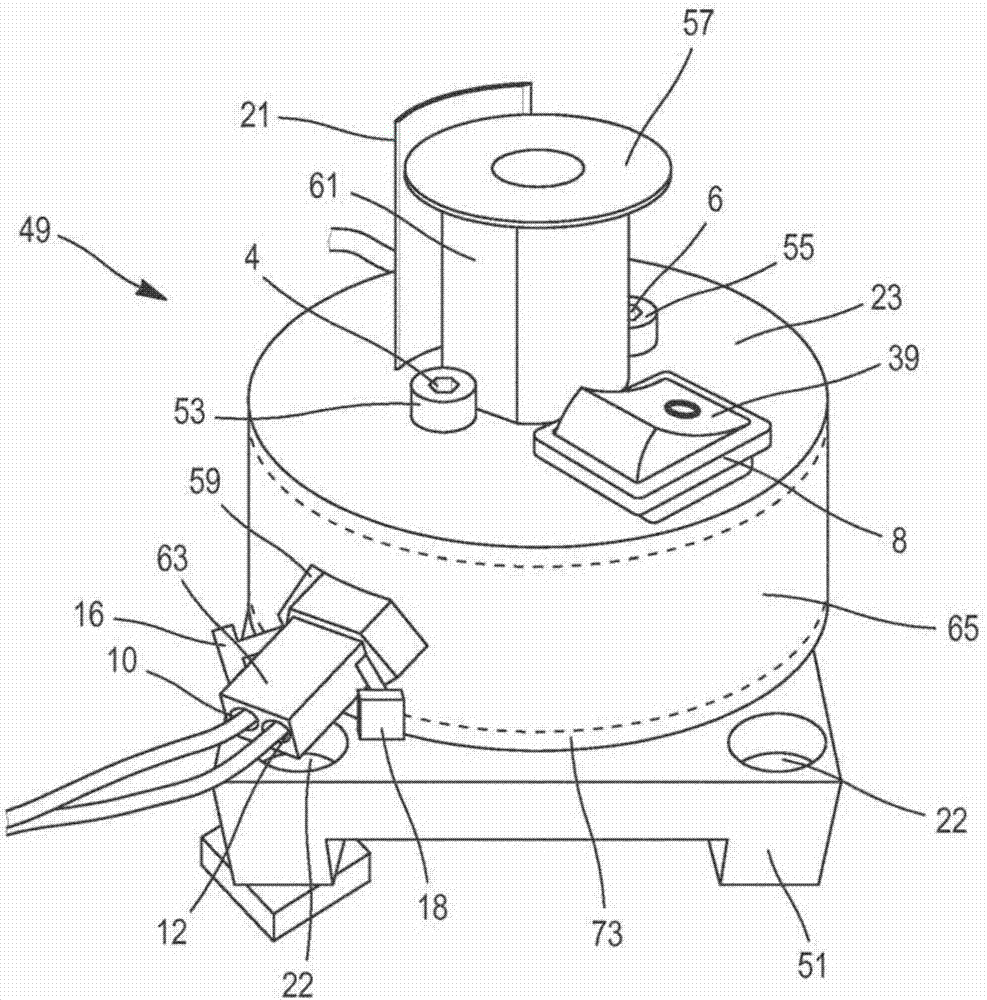
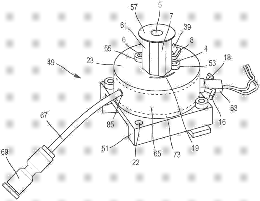
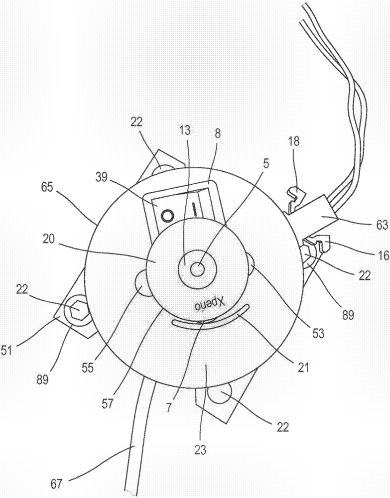
[0023] A lens holder device and method of marking an ophthalmic lens using a lens holder is presented herein. This improved device and method allows the user to consistently orient and position the lens on the lens holder to achieve marking at the desired location while reducing user error and the chance of incorrectly marking or damaging the lens, This saves time and reduces manufacturing costs.

[0024] Other objects, features and advantages of the present disclosure will become apparent from the following detailed description. It should be understood, however, that the detailed description and specific examples, while indicating particular embodiments of the invention, are given by way of illustration only, since various changes and modifications within the spirit and scope of the invention will be apparent from such detailed description. It will become apparent to those skilled in the art. Unless the scope is expressly and clearly defined in this disclosure or unless the...


PUM


Abstract

A lens holder assembly (49) and method of using the lens holder assembly (49) to mark an ophthalmic lens (3) is provided. The lens holder assembly (49) comprises a stem (61) having a central axis and a first opening (5) extending along the central axis of the body (65), a second opening (7) integrated within the stem (61) such that the second opening (7) is substantially parallel to the first opening (5), and at least one illumination source positioned within the second opening (7). The illumination source is capable of emitting light through the second opening (7) for illuminating at least a portion of an ophthalmic lens (3). At least a portion of the lens (3) is placed over the first opening (5). Suction is applied to the lens (3), and a marking is applied to a surface of the lens (3).

Description

technical field [0001] The present invention relates to a lens holder and a method of marking an ophthalmic lens using the lens holder. Background technique [0002] Pad printing is one method of marking ophthalmic lenses. Such methods may include subjecting the surface of the lens to be marked to corona discharge, flame, or ionized air in order to increase the surface energy and thereby improve the adhesion of the surface to be marked. The lenses can then be marked using pad printing or screen printing with special marking inks. The ink is then dried. Thereafter, if desired, ink components can be removed with a suitable solvent. [0003] Pad printing methods can present difficulties in consistently and accurately positioning the lens relative to the frame when placing indicia, such as stamps or engravings, at desired locations on the lens, especially tinted or polarized lenses. Contents of the invention [0004] A lens holder assembly for use with a lens marking appar...

Claims


Application Information

Patent Timeline
IPC IPC(8): B29D11/00B24B13/005
CPCB24B13/0055B29D11/00317B29D11/00009G02C7/021
Inventor P·A·麦克利曼斯J·格拉
Owner ESSILOR INT CIE GEN DOPTIQUE
Why Eureka
Try Eureka