Electric vehicle charging system

A technology for electric vehicles and charging systems, applied in electric vehicles, motor vehicles, collectors, etc., can solve problems such as traffic congestion, breakdown without electricity, and high power consumption.

Active Publication Date: 2018-05-04
江佳辉
View PDF6 Cites 0 Cited by
  • Summary
  • Abstract
  • Description
  • Claims
  • Application Information

AI Technical Summary

Problems solved by technology

Even if driving a short distance in the city, users need to pay attention to the remaining power of the electric vehicle, otherwise it is easy to break down due to no electricity halfway
The scheme of setting up charging equipment on the roadside similar to two-wheeled battery vehicles is not very suitable for electric vehicles. On the one hand, the footprint of electric vehicles is much larger than that of two-wheeled battery vehicles, and fixed-point parking and charging may cause traffic congestion. On the other hand, electric vehicles consume much more power than two-wheeled battery vehicles. In the absence of significant breakthroughs in battery charging technology, it takes a long time to stop and charge halfway.

Method used


Image

  • Electric vehicle charging system
  • Electric vehicle charging system
  • Electric vehicle charging system

Examples


Embodiment 1

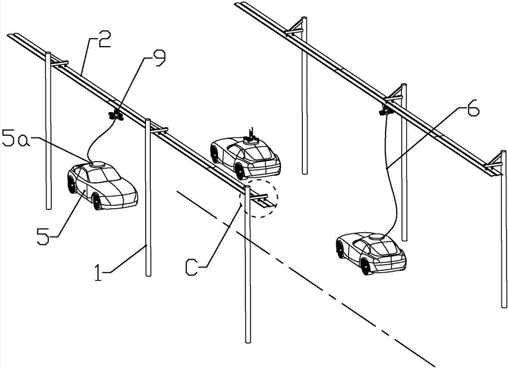
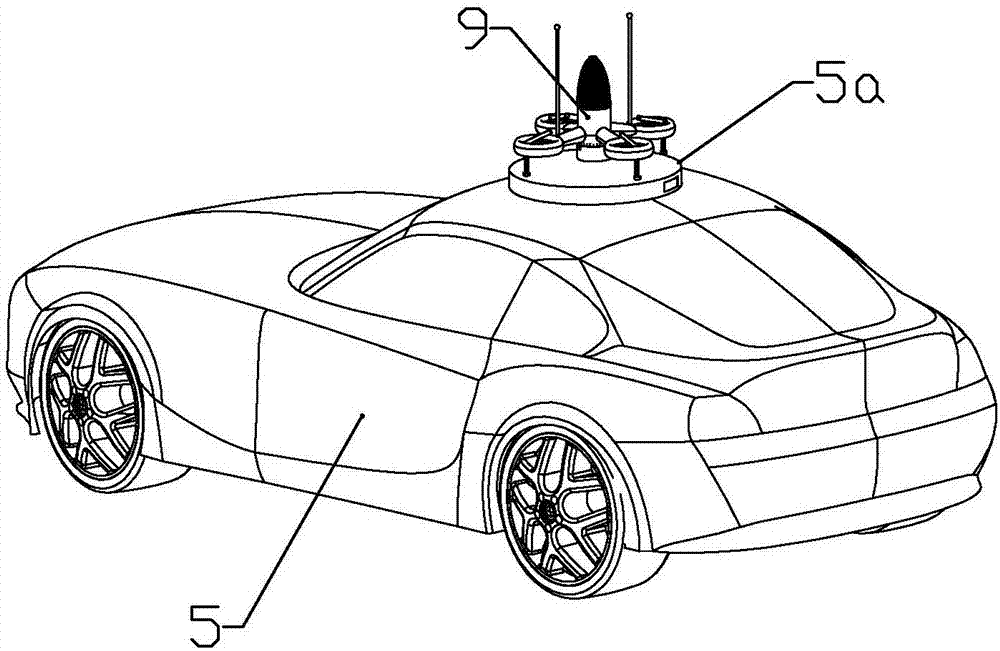
[0065] according to Figures 1 to 5 As shown, this embodiment is an electric vehicle charging system, including a plurality of power transmission poles 1 fixedly installed on both sides of the road, and power transmission guide rails 2 installed between the power transmission poles on the same side of the road, which can be close to the power transmission guide rails The aircraft 9 flying below, and the wire 6 connected between the electric vehicle and the aircraft to transmit electric energy from the power transmission rail to the electric vehicle. The power transmission guide rail is connected to the power supply network.

[0066] The power transmission guide rails include two parallel ones, and the upper end of the aircraft is connected with a pole 98 that is slidingly and electrically connected to the two power transmission guide rails, and the pole is electrically connected to one end of the wire.

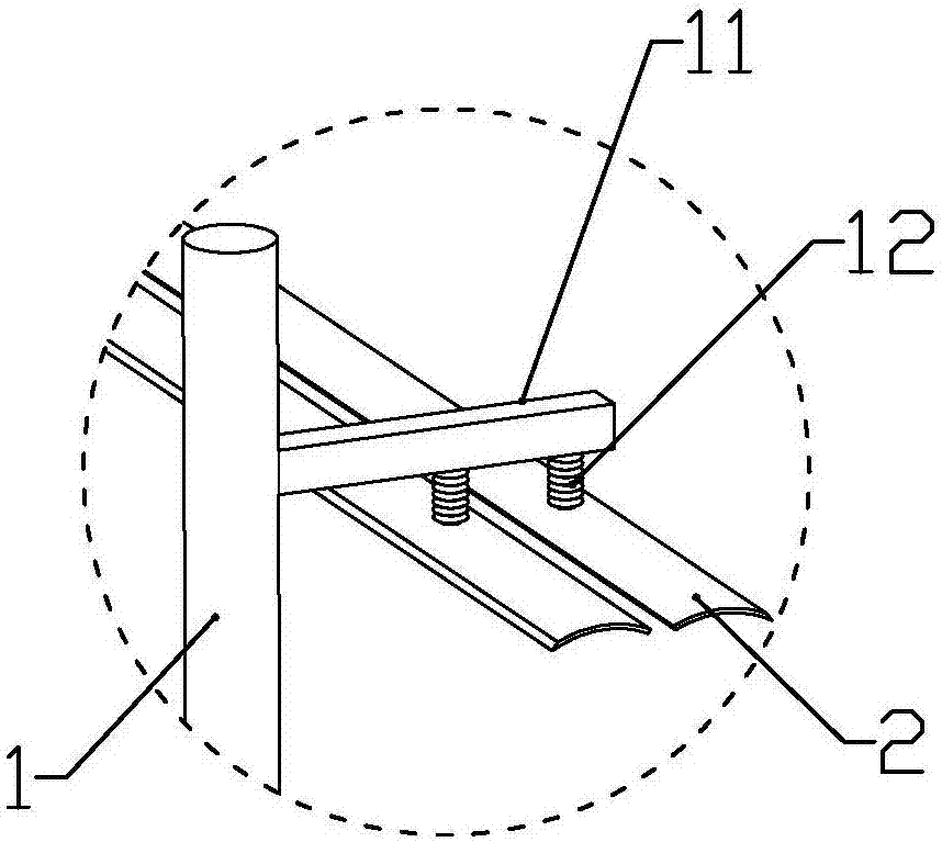
[0067] The side of the upper part of the power transmission pole facing ...

Embodiment 2

[0077] combine Figure 6 to Figure 12 As shown, this embodiment makes the following improvements on the basis of Embodiment 1: the aircraft includes a main body 91, and the main body includes a circular tube-shaped fan mounting portion 910, which is connected to the outer periphery of the fan mounting portion and connected to the fan Four equidistantly arranged connecting pipes 912 communicated with the installation part, and an air outlet ring 911 connected to the outer end of each connecting pipe and communicated with the corresponding connecting pipe.

[0078] The upper bracket 9101 is connected to the fan installation part above the connecting pipe, and the upper driving fan 951 is installed on the upper bracket; the lower bracket 9102 is connected to the fan installation part below the connecting pipe, and the lower bracket is installed There is a lower driving fan 952; the turning direction of the upper driving fan is opposite to that of the lower driving fan, and the in...

Embodiment 3

[0094] combine Figure 13 to Figure 14 In this embodiment, the following improvements are made on the basis of Embodiment 2: a landing gear joint 9110 is formed on the inner circumference of each of the air outlet rings away from the connecting pipe, and a landing gear 93 is connected to each of the landing gear joints The landing gear includes a connecting pipe body 931 that is fixedly connected with the landing gear joint and communicates with the inside of the air outlet ring through the landing gear joint, and the sliding pipe 932 that is slidably installed in the connecting pipe body is close to the landing gear joint with the connecting pipe body One end of the support rod 935 is rotatably connected, the second electromagnet 936 connected to the end of the support rod away from the landing gear joint is used to attract and tighten the top of the electric vehicle, and the connecting rod 934 is respectively rotatably connected to the middle part of the sliding tube and the ...


PUM


Abstract

The invention discloses a power supply system for an electric vehicle, which comprises a plurality of power transmission poles fixedly installed on both sides of the road, a power transmission guide rail installed between the power transmission poles on the same side of the road, and an aircraft that can fly close to the bottom of the power transmission guide rail. And the wires used to transmit electric energy from the power transmission guide rail to the electric vehicle connected between the electric vehicle and the aircraft; An electrically connected electric pole, the electric pole is electrically connected with one end of the wire; the invention flies the aircraft close to the power transmission guide rail, and transmits the electric energy to the electric vehicle through the electric wire through the electric pole, so that the electric vehicle does not need to stop It can be charged, and the aircraft can fly away from the power transmission rail at any time when the electric vehicle is fully charged or under other conditions, which will not restrict the free driving of the electric vehicle.

Description

technical field [0001] The invention belongs to the field of supporting systems for electric vehicles, and in particular relates to a charging system for electric vehicles. Background technique [0002] With the popularization of electric vehicles, the problem of inconvenient charging of electric vehicles has become increasingly prominent; currently, users who buy electric vehicles are generally limited to commuting in the city, and users who need to go out for a long time still prefer to use fuel vehicles. Even for short-distance driving in the city, users need to pay attention to the remaining power of the electric vehicle, otherwise it is easy to break down without electricity halfway. The scheme of setting up charging equipment on the roadside similar to two-wheeled battery vehicles is not very suitable for electric vehicles. On the one hand, the footprint of electric vehicles is much larger than that of two-wheeled battery vehicles, and fixed-point parking and charging ...

Claims


Application Information

Patent Timeline
Patent Type & Authority Patents(China)
IPC IPC(8): B64C27/10B64C25/20B64C25/22B60L5/38
CPCB64C25/20B64C25/22B64C27/10B60L5/38B64U10/10B64U2101/00
Inventor 江佳辉虞丽丽
Owner 江佳辉
Why Eureka
Try Eureka