Sanitary change-over valve and assembly comprising a change-over valve of this type

A switching valve and hygienic technology, which is applied to indoor sanitary pipeline devices, multi-port valves, control valves, etc., can solve problems such as the inability to adapt the switching valve and the complex space requirements of the switching valve structure.

Inactive Publication Date: 2017-10-17
NEOPERL
View PDF11 Cites 2 Cited by
  • Summary
  • Abstract
  • Description
  • Claims
  • Application Information

AI Technical Summary

Problems solved by technology

However, the switching valve known from EP 1 664 957 B1 cannot be adapted to the different requirements of different applications, especially also in the low-pressure range
Furthermore, the known switching valves are relatively complex in design and require a corresponding space requirement

Method used


Image

  • Sanitary change-over valve and assembly comprising a change-over valve of this type
  • Sanitary change-over valve and assembly comprising a change-over valve of this type
  • Sanitary change-over valve and assembly comprising a change-over valve of this type

Examples


Embodiment Construction

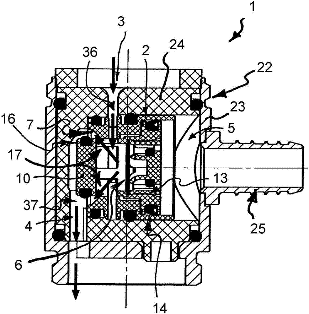
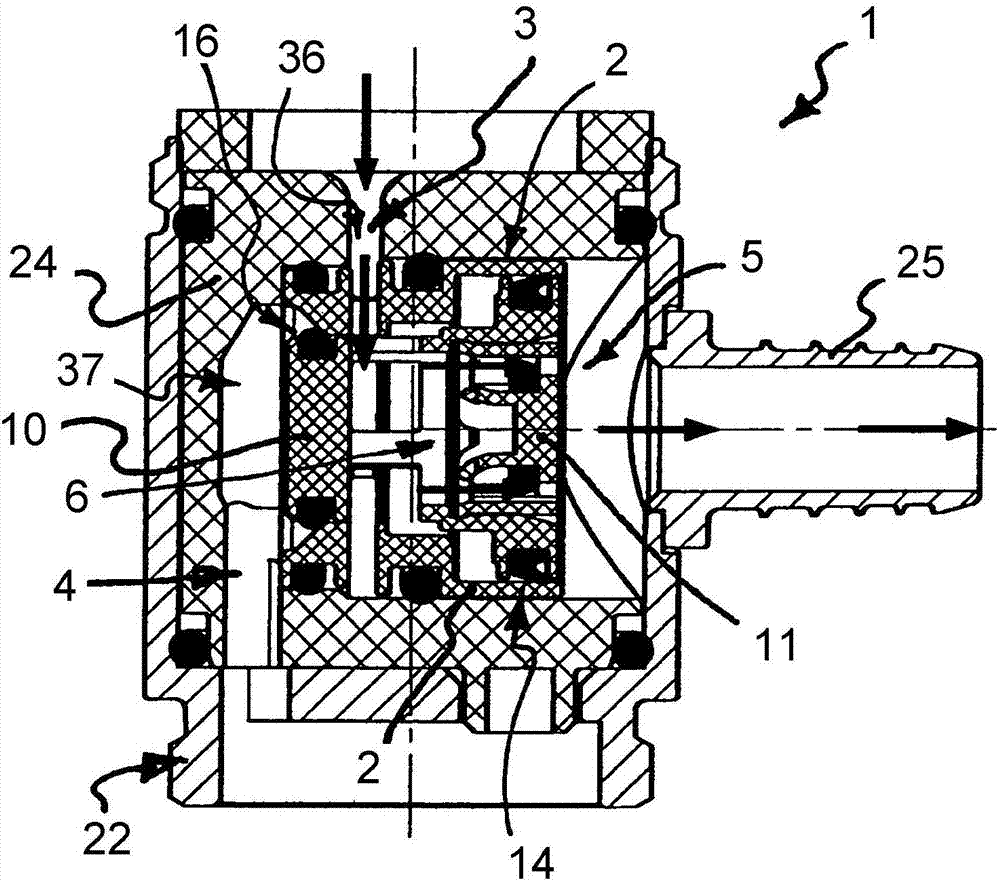
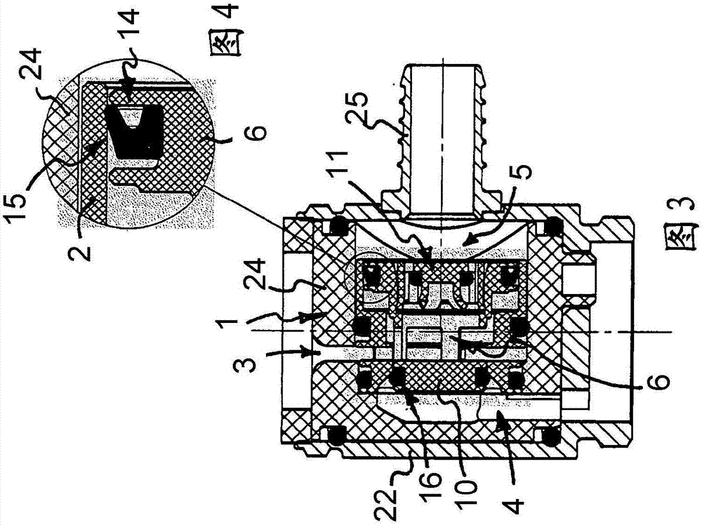
[0061] exist Figures 1 to 39 The hygienic switchover valve 1 is shown in various embodiments and application examples. The changeover valve 1 is intended here to be installed in a water line in order to selectively allow water to flow out of one water outlet or out of the other water outlet when required. The hygienic changeover valve 1 has a valve housing 2 with a valve inlet 3 and two selectively actuatable valve outlets 4 , 5 . A valve piston 6 is displaceably guided in the valve housing 2, which can be moved, for example in figure 1 The first switching position shown in the figure 2 movement between the second switching position shown opposite thereto. in accordance with figure 1 In the first switching position of the water is directed through the flow path through the first valve outlet 4, while the fluid is in accordance with figure 2 The flow path leading through the second valve outlet 5 is reversed in the second switching position of the second valve, once the...


PUM


Abstract

The invention relates to a sanitary change-over valve (1) comprising a valve housing (2) which has a valve inlet (3) and two selectively controllable valve outlets (4, 5), a valve piston (6) that can be moved from a first switch-over position, in which the fluid is conducted via a flow path passing through a first valve outlet (4), into a second switch-over position, in which the fluid is conducted via a flow path passing through a second valve outlet (5), as soon as the stretch of the second flow path leading from the change-over valve (1) has been released. The valve piston (6) is designed as a hollow body, through which the fluid is conducted by means of at least one piston inlet (9) positioned on the piston circumference in the course of at least one of the flow paths. The change-over valve according to the invention is characterised in that the fluid conducted by means of the at least one piston inlet (9) is led, in the course of the second flow path, through a first piston outlet provided on the piston end face facing away from the piston head (10), and in that a flow throttle (12), a flow-control valve (11) or a check valve is provided in the first piston outlet.

Description

technical field [0001] The invention relates to a hygienic switching valve, which has a valve housing and a valve piston, the valve housing has a valve inlet and two selectively actuatable valve outlets, the valve piston can be switched from a first switching position - the fluid is in the second In a switching position directed through the flow path through the outlet of the first valve - moving into the second switching position, once the section of the second flow path leading from the switching valve has been released, the fluid is in the second switching position is guided through a flow path through the second valve outlet, wherein the valve piston is formed as a hollow body through which the fluid is guided in the course of at least one of the flow paths through a ring arranged on the piston ring at least one piston inlet. [0002] The invention is also directed to a sanitary assembly having a switching valve of the type mentioned at the outset. Background technique ...

Claims


Application Information

Patent Timeline
Patent Type & Authority Applications(China)
IPC IPC(8): F16K11/00F16K11/044F16K11/10F16K15/02E03C1/02
CPCE03C1/023E03C2201/30F16K11/00F16K11/0445F16K11/105F16K15/02E03C1/0408Y10T137/2683F16K11/025
Inventor B·迈耶
Owner NEOPERL
Why Eureka
Try Eureka