
Draining device and method for deep foundation pit pool construction in thermal power plant confined space

A technology for drainage devices and deep foundation pits. It is applied in the direction of infrastructure engineering and construction. It can solve the problems of many impurities in foundation pit water, single drainage method, and inability to effectively prevent them, so as to improve stability, realize back-and-forth conversion, and avoid The effect of water clogging

Pending Publication Date: 2020-01-10
POWERCHINA SEPCO1 ELECTRIC POWER CONSTR CO LTD
View PDF0 Cites 1 Cited by
  • Summary
  • Abstract
  • Description
  • Claims
  • Application Information

AI Technical Summary

Problems solved by technology

For the drainage of deep foundation pit pool construction in the limited space of thermal power plants, the inventor believes that the current drainage devices for deep foundation pit pool construction in thermal power plants mainly have the following disadvantages: 1. The drainage method of thermal power plant drainage devices is single and widely used The drainage pump is used for drainage, and some special situations cannot be effectively prevented; ②Due to the complex environment in the foundation pit, there are many impurities in the water in the foundation pit, and there is a problem that the drainage device is easy to block the water inlet pipe during use; ③The traditional drainage device is not conducive to Used in confined spaces and deep foundation pits

Method used


Image

  • Draining device and method for deep foundation pit pool construction in thermal power plant confined space
  • Draining device and method for deep foundation pit pool construction in thermal power plant confined space
  • Draining device and method for deep foundation pit pool construction in thermal power plant confined space

Examples


Embodiment 1

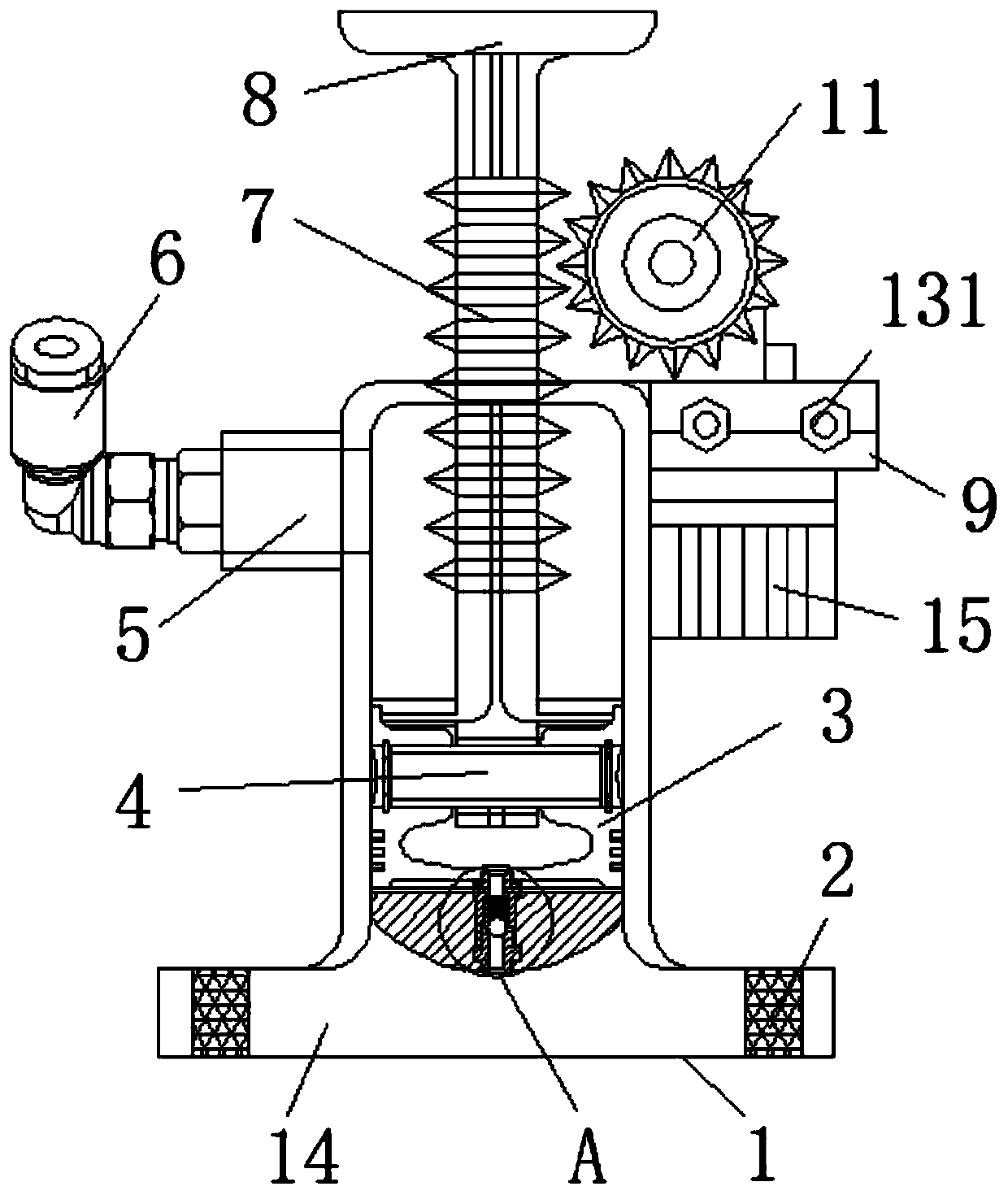
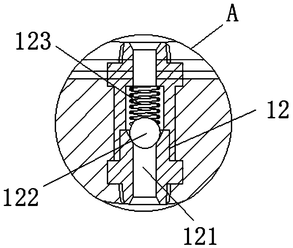
[0033] A drainage device for construction of a deep foundation pit pool in a confined space of a thermal power plant, including a housing 1, a transmission mechanism, a plug body 3, a one-way valve 12 and a power source, the bottom of the housing 1 is provided with an opening, and the opening passes through the one-way valve 12 Connect the water inlet pipe 14, the T-shaped connection between the water inlet pipe 14 and the shell 1, the water inlet pipe 14 is installed with the filter screen 2, the worm 7 extends from the top outside of the shell 1 to the inside of the shell 1, and the end of the worm 7 is connected The plug body 3, the housing 1 below the plug body 3 is equipped with a one-way valve 12, and the one-way valve 12 can close the housing 1; the power source is connected to the worm gear 11 and the worm screw 7 assembly. In this embodiment, the power source is a motor 10 , and the transmission mechanism is a worm gear 11 and a worm 7 mechanism, including the meshing ...

Embodiment 2

[0048] Embodiment 2 discloses a drainage method for construction of a deep foundation pit pool in a confined space of a thermal power plant, which specifically includes the following steps:

[0049] Select manual mode and electric mode;

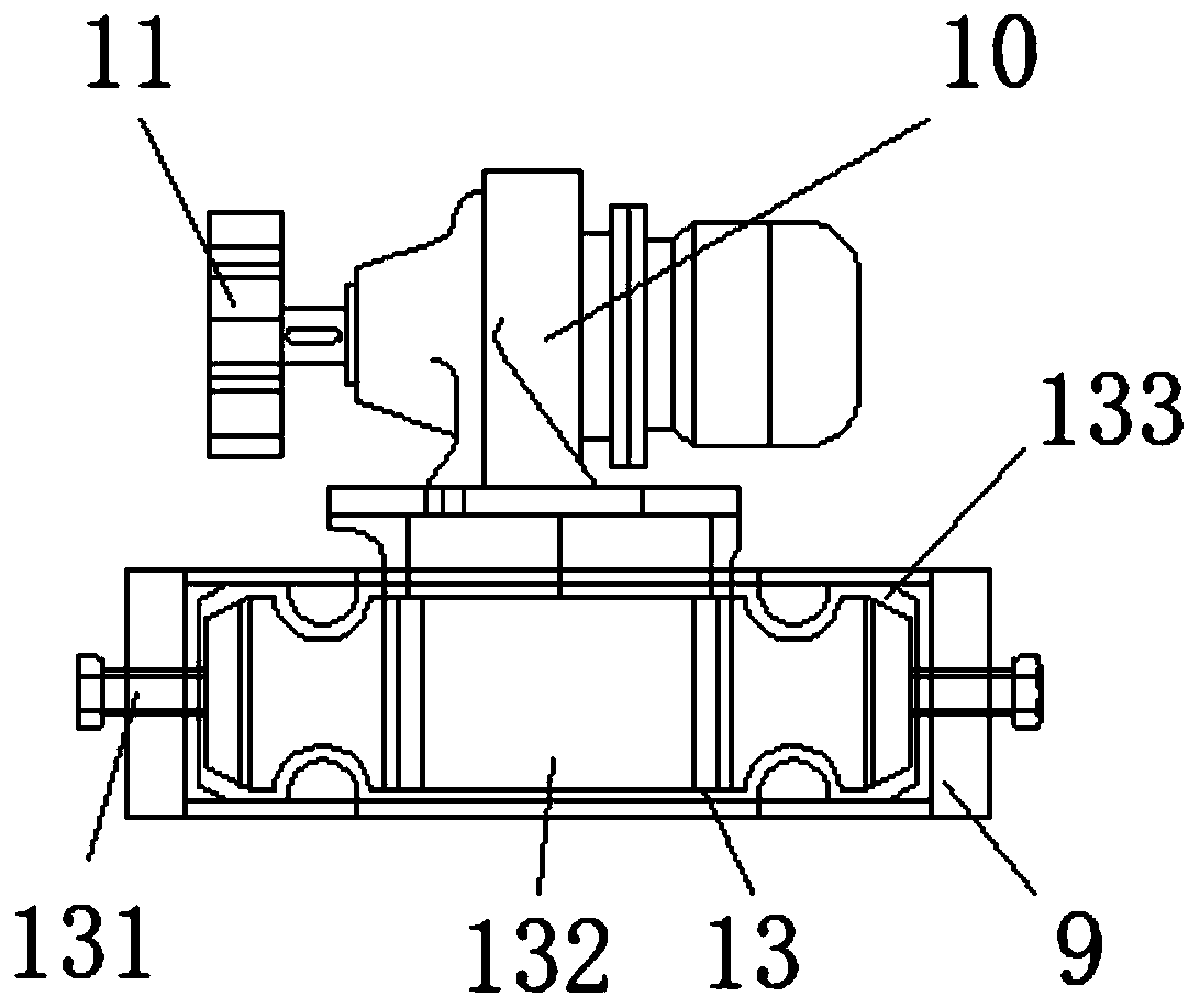
[0050] When the electric mode is selected, the slider 132 is pushed, and the slider 132 slides in the slide rail 133 to drive the motor 10 to move, so that the worm wheel 11 on the output shaft of the motor 10 and the worm 7 can be engaged with each other, and through the fixing bolt 131 The position of the motor 10 is fixed to ensure the stability of the motor 10 during operation;

[0051] The motor 10 drives the worm 7 to move up and down through the meshing of the worm wheel 11 and the worm 7, and the worm 7 pulls the plug body 3 to reciprocate in the housing 1, and the inner wall of the housing 1 and the plug body 3 are closely fitted. Form a negative pressure area in the housing 1, which can pump the liquid inside the water inlet pipe 1...


PUM


Abstract

The invention discloses a draining device and method for deep foundation pit pool construction in thermal power plant confined space. The device comprises a shell, a transmission mechanism, a plug body, a one-way valve and a power source. An opening is formed in the bottom of the shell, the opening is connected with a water inlet pipeline through the one-way valve, the water inlet pipeline is in T-type connection with the shell, the water inlet pipeline is provided with a filter net, a worm extends into the shell from the outer side of the top of the shell, the tail end of the worm is connected with the plug body, the position, below the plug body, of the shell is provided with the one-way valve, the one-way valve can seal the shell, and the power source is connected with a worm and gear assembly. The device is provided with two water inlets, liquid is filtered in a water inlet pipe, inlet water blockage is avoided, the device can be used in the confined space and in a foundation pit,and pulling of equipment like a wire can be avoided.

Description

technical field [0001] The invention relates to the field of drainage, in particular to a drainage device and method for construction of a deep foundation pit pool in a confined space of a thermal power plant. Background technique [0002] The foundation pit is an earth pit excavated at the foundation design position according to the base level and foundation plane size. Before excavation, the excavation plan should be determined according to the geological and hydrological data, combined with the conditions of the nearby buildings, and the waterproof and drainage work should be done well. If the excavation is not deep, the side slope can be used to stabilize the soil slope, and the slope size is determined according to the relevant construction engineering regulations. A deep foundation pit refers to a project where the excavation depth exceeds 5 meters (including 5 meters), or the basement has more than three floors (including three floors), or the depth does not exceed 5...

Claims


Application Information

Patent Timeline
Patent Type & Authority Applications(China)
IPC IPC(8): E02D19/06
CPCE02D19/06
Inventor 李江涛吴立晴邵德川方唯张良程亚洲王庆涛
Owner POWERCHINA SEPCO1 ELECTRIC POWER CONSTR CO LTD
Learn More