A method for plugging gas pipelines and a device for realizing the method

A technology of gas pipeline and plugging method, which is applied in the direction of pipe components, pipes/pipe joints/pipe fittings, mechanical equipment, etc., which can solve the problems of weakened compression effect of sealing briquettes, loosening, secondary leakage, etc., to ensure leakage work Up to the standard, not easy to secondary leakage, convenient plugging work

Inactive Publication Date: 2019-04-16
上海安宏建设工程有限公司
View PDF6 Cites 0 Cited by
  • Summary
  • Abstract
  • Description
  • Claims
  • Application Information

AI Technical Summary

Problems solved by technology

[0004] The above-mentioned plugging method is mainly to rotate and adjust the fine-tuning anti-loosening screw to press the soft sealing block on the leakage point. However, since the gas pipeline is often buried underground, the fine-tuning anti-loosening screw is easily corroded by corrosive fluid. loosening, resulting in the weakening of the compression effect of the sealing briquetting block on the leakage point, and secondary leakage is prone to occur after a period of plugging

Method used


Image

  • A method for plugging gas pipelines and a device for realizing the method
  • A method for plugging gas pipelines and a device for realizing the method
  • A method for plugging gas pipelines and a device for realizing the method

Examples


Embodiment 1

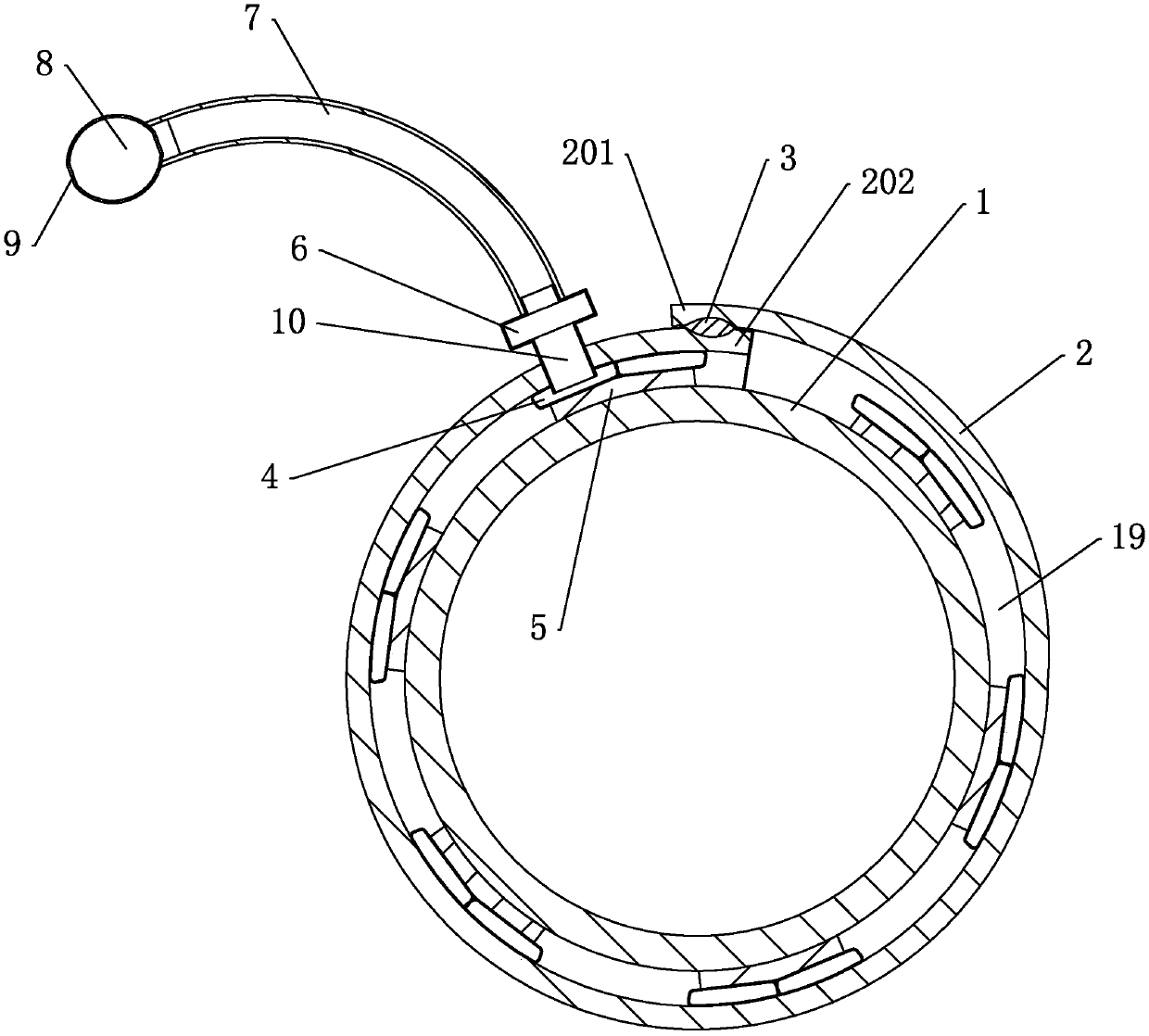
[0038] Embodiment 1: A kind of plugging method of gas pipeline, refer to figure 1 and figure 2 As shown, the method includes the following steps in sequence:

[0039] a. The emergency repair personnel of the gas company arrive at the site as soon as possible, prepare fire extinguishers, explosion-proof fans, etc., and use experience or equipment to find out the specific leakage point of gas pipeline 1 according to the site conditions, and clean up the anti-corrosion substances, rust and impurities on the pipelines around the leakage point. Clean, so that the surface of the gas pipeline 1 around the leakage point is flat;

[0040]b. According to the diameter of the gas pipeline 1, select a leakage plugging device that matches the diameter of the gas pipeline 1, wrap the soft body 2 on the leakage plugging device on the gas pipeline 1 in an annular shape, and put the The first end portion 201 and the second end portion 202 are fixed together, the soft body 2 and the gas pipel...

Embodiment 2

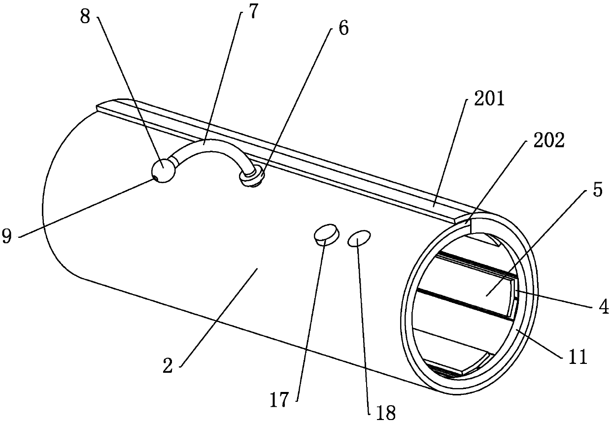
[0043] Embodiment 2: a plugging device, used to realize the above embodiment 1, such as figure 1 As shown in the figure, it includes a soft body 2 that is wrapped around the gas pipeline 1. The soft body 2 is made of soft material and can be curled and folded to form a ring. The two ends of the soft body 2 are the first ends respectively. part 201 and the second end part 202, after the soft body 2 is tightly wound on the gas pipeline 1, the first end part 201 and the second end part 202 are fixed by glue Glue 3, preferably acrylic adhesive, acrylic adhesive has adhesiveness and anti-corrosion, the first end 201 and the second end 202 are fixed and bonded by coating, which can avoid the first end 201 and the second end 202. The connection between one end portion 201 and the second end portion 202 is affected by the corrosion of corrosive substances, and the bonded soft body 2 is tightly attached to the outer circumferential surface of the gas pipeline 1 .

[0044] combine fi...

Embodiment 3

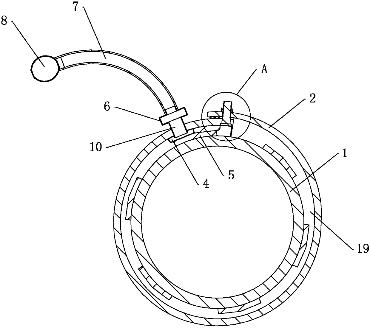
[0048] Embodiment 3: a leakage plugging device, which is different from Embodiment 2 in that, as image 3 and Figure 4 As shown, the first end portion 201 is provided with a through hole 14 and a nut 13 penetrating the inner and outer surfaces of the first end portion 201, the second end portion 202 is fixedly connected with a bolt 12, and the bolt 12 passes through the through hole 14 and is connected to the nut 13. The first end 201 and the second end 202 are fixed by screw thread; the first end 201 facing the inner surface of the gas pipeline 1 is fixedly connected with an inclined first ratchet 15, and the first ratchet 15 is upwards. It is gradually inclined to the right, the outer surface of the first end 201 is fixedly connected with the inclined second ratchet 16, the inclination direction of the second ratchet 16 is consistent with the inclination direction of the first ratchet 15, and the first ratchet 15 and the second ratchet teeth 16 engage and interfere with ea...


PUM


Abstract

The invention discloses a leaking stoppage method and a leaking stoppage device for a gas pipeline, wherein the leaking stoppage method comprises the following steps that b, a soft body of the leaking stoppage device is wound and arranged on the gas pipeline in a sleeving manner, the soft body and the gas pipeline are fastened in a sleeving mode, a sealing body on the soft body is tightly attached to the outer circumferential surface of the gas pipeline, a gap between the soft body and the gas pipeline is sealed in the width direction of the soft body, an airtight cavity is formed between the soft body and the gas pipeline, leaking points are correspondingly covered with compaction blocks on the leaking stoppage device, and the amount of gas leaked from the leaking points is reduced; c, an air valve on an air nozzle is opened, an air bag is inflated in a manner of extruding a rubber ball, compaction blocks on the air bag tightly press the leaking points, the leaking points are sealed, the air bag is continuously inflated until the leaking points are completely sealed by the compaction blocks, the air valve is closed to keep the leaking points always tightly pressed by the compaction blocks, leaking stoppage work is more convenient and labor-saving, the air compaction effect is remarkable, and secondary leakage is not prone to generating.

Description

technical field [0001] The invention relates to a leakage plugging technology of a gas pipeline, in particular to a leakage plugging method for a gas pipeline and a device for realizing the method. Background technique [0002] With the continuous improvement of living standards, people have higher and higher requirements for residential interior decoration, and the laying method of indoor gas pipelines directly affects the interior decoration effect of residential buildings. Because the gas pipeline is buried, it is not easy to be found after the pipeline leaks, and it is difficult to deal with the leakage fault, which lays a hidden danger for the safety of the gas pipeline. [0003] At present, in the prior art, in a Chinese patent document with the authorization announcement number CN101900238B, a method for plugging gas pipelines without continuous gas and welding is recorded, and a soft sealing pressure block matching the size of the leakage point is selected. , placed...

Claims


Application Information

Patent Timeline
Patent Type & Authority Patents(China)
IPC IPC(8): F16L55/17F16L55/163
CPCF16L55/163F16L55/1705
Inventor 杨争战陆伯彦陆伯忠冯伟戴红兵陈运筹
Owner 上海安宏建设工程有限公司
Why Eureka
Try Eureka