Power supply connection device for power utilization equipment

A technology for electrical equipment and joint devices, applied in the direction of coupling devices, devices for preventing contact with live contacts, parts of connecting devices, etc. To achieve the effect of convenient use, simple structure and high safety of electricity consumption

Active Publication Date: 2017-11-21
广西广开电气有限公司
View PDF3 Cites 10 Cited by
  • Summary
  • Abstract
  • Description
  • Claims
  • Application Information

AI Technical Summary

Problems solved by technology

[0002] The power supply base is an electrical device that provides an interface for the electrical equipment. The plug connector is directly connected to the electrical equipment. When in use, the plug connector is inserted into the power supply base to be powered on. In the socket, the conductive sheet is generally exposed in the insertion slot, and the conductive sheet is directly connected to the mains. When the plug connector is inserted into the insertion slot, it will contact the conductive sheet, thereby realizing power supply to the electrical equipment. However, this kind of conductive sheet is also easily touched by metal sheets or metal rods. If some people (such as young children) lack safety awareness, when inserting metal sheets or metal rods into the insertion slot Sometimes, electric shock safety accidents will occur, and in serious cases, people will die. Therefore, the traditional power supply stand has great potential safety hazards; When the connector is connected, it is easy to separate or loosen the plug connector and the power supply base. Therefore, it is easy to cause accidental power failure of the electrical equipment, and it is easy to affect the electrical equipment. At the same time, it will also cause the user's data to be lost.

Method used


Image

  • Power supply connection device for power utilization equipment
  • Power supply connection device for power utilization equipment
  • Power supply connection device for power utilization equipment

Examples


Embodiment Construction

[0023] All features disclosed in this specification, or steps in all methods or processes disclosed, may be combined in any manner, except for mutually exclusive features and / or steps.

[0024] Any feature disclosed in this specification (including any appended claims, abstract and drawings), unless expressly stated otherwise, may be replaced by alternative features which are equivalent or serve a similar purpose. That is, unless expressly stated otherwise, each feature is one example only of a series of equivalent or similar features.

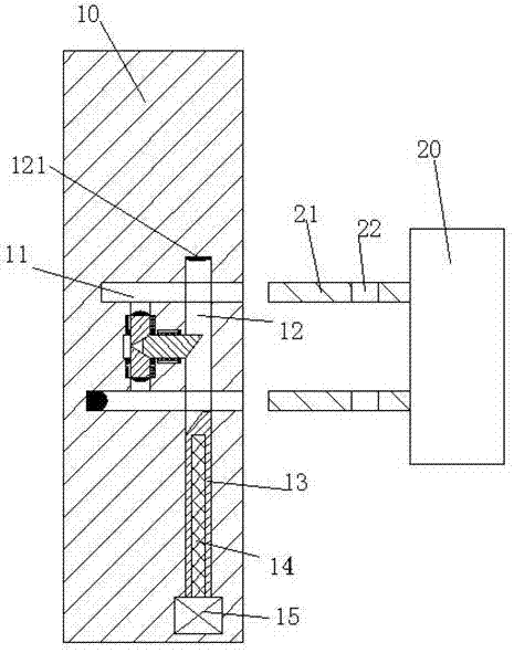
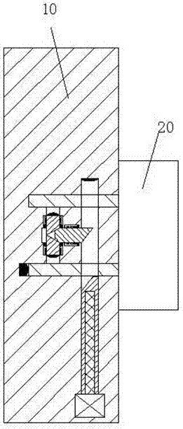
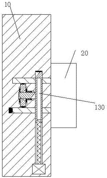
[0025] Combine below Figure 1-5 The present invention will be described in detail.

[0026] refer to Figure 1-5 , according to an embodiment of the present invention, a power supply joint device for electrical equipment, including a socket socket 10 fixedly installed in the wall and a plug connector 20 connected to the electrical equipment, the upper and lower sides of the socket socket 10 Insertion grooves 11 are symmetrically arranged, ...


PUM


Abstract

A power supply connection device for power utilization equipment comprises a socket and a plug, wherein the socket is fixedly arranged in a wall body, the plug is connected with the power utilization equipment, insertion grooves are vertically and symmetrically formed in the socket, a longitudinal sliding groove is formed between the two insertion grooves, a rectangular sliding groove is also formed in the socket, extends upwards and downwards and penetrates through the insertion grooves, a horizontal sliding groove is formed between the rectangular sliding groove and the longitudinal sliding groove and is used for communicating the rectangular sliding groove and the longitudinal sliding groove, a sliding strip is arranged at a lower end of the rectangular sliding groove in a sliding way, an internal threaded hole is formed in the sliding strip, a lifting threaded rod is arranged in the internal threaded hole in a threaded matching way, a lower end of the lifting threaded rod is in power connection with a lifting motor, the lifting motor is fixedly arranged at the bottom of the rectangular sliding groove, longitudinal sliding arms are vertically and symmetrically arranged in the longitudinal sliding groove, first extrusion inclined surfaces are arranged on ends, opposite to each other, of the two longitudinal sliding arms, conductive sheets are arranged at ends, facing the insertion grooves, of the two longitudinal sliding arms and are connected with a mains supply, and a horizontal sliding arm is arranged in the horizontal sliding groove.

Description

technical field [0001] The invention relates to the field of power supply for electric equipment, in particular to a power supply joint device for electric equipment. Background technique [0002] The power supply base is an electrical device that provides an interface for the electrical equipment. The plug connector is directly connected to the electrical equipment. When in use, the plug connector is inserted into the power supply base to be powered on. In the socket, the conductive sheet is generally exposed in the insertion slot, and the conductive sheet is directly connected to the mains. When the plug connector is inserted into the insertion slot, it will contact the conductive sheet, thereby realizing power supply to the electrical equipment. However, this kind of conductive sheet is also easily touched by metal sheets or metal rods. If some people (such as young children) lack safety awareness, when inserting metal sheets or metal rods into the insertion slot Sometim...

Claims


Application Information

Patent Timeline
Patent Type & Authority Applications(China)
IPC IPC(8): H01R13/70H01R13/629H01R13/44H01R13/627
CPCH01R13/44H01R13/627H01R13/629H01R13/701
Inventor 潘军权
Owner 广西广开电气有限公司
Why Eureka
Try Eureka