Novel power supply jointing apparatus

A joint device, a new type of technology, is applied in the direction of the coupling device, the parts of the connection device, and the device for preventing contact with live contacts, etc. It can solve problems such as death, separation of the plug connector and the power supply seat, and loss of user data. The effect of high electrical safety, convenient use and simple structure

Inactive Publication Date: 2018-03-27
广西景曜电子科技有限公司
View PDF5 Cites 1 Cited by
  • Summary
  • Abstract
  • Description
  • Claims
  • Application Information

AI Technical Summary

Problems solved by technology

[0002] The power supply base is an electrical device that provides an interface for the electrical equipment. The plug connector is directly connected to the electrical equipment. When in use, the plug connector is inserted into the power supply base to be powered on. In the socket, the conductive sheet is generally exposed in the insertion slot, and the conductive sheet is directly connected to the mains. When the plug connector is inserted into the insertion slot, it will contact the conductive sheet, thereby realizing power supply to the electrical equipment. However, this kind of conductive sheet is also easily touched by metal

Method used


Image

  • Novel power supply jointing apparatus
  • Novel power supply jointing apparatus
  • Novel power supply jointing apparatus

Examples


Embodiment Construction

[0025] All the features disclosed in this specification, or all disclosed methods or steps in the process, except for mutually exclusive features and / or steps, can be combined in any manner.

[0026] Any feature disclosed in this specification (including any appended claims, abstract and drawings), unless specifically stated, can be replaced by other equivalent or equivalent alternative features. That is, unless otherwise stated, each feature is just one example of a series of equivalent or similar features.

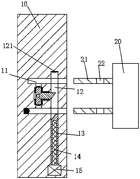
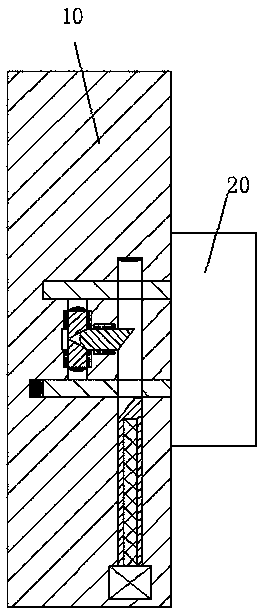
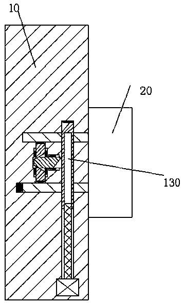
[0027] Combine below Figure 1-6 The present invention will be described in detail.

[0028] Reference Figure 1-6 According to an embodiment of the present invention, a new type of power supply joint device includes a socket 10 fixedly installed in the wall and a socket 20 connected with electrical equipment. The socket 10 is symmetrically arranged with inserts. Slot 11, a longitudinal sliding groove 17 is provided between the upper and lower insertion grooves 11, the socke...


PUM


Abstract

Disclosed is a novel power supply jointing apparatus. The novel power supply jointing apparatus comprises an inserting-connecting base fixedly mounted in a wall body, and an inserting-connecting end connected with electrical equipment; inserting grooves are symmetrically formed in the inserting-connecting base up and down; a longitudinal sliding groove is formed between the upper and lower inserting grooves; a rectangular sliding groove which extends up and down and runs through the inserting grooves is also formed in the inserting-connecting base; a transverse sliding groove connected with the rectangular sliding groove and the longitudinal sliding groove is formed between the rectangular sliding groove and the longitudinal sliding groove; a sliding strip is glidingly mounted at the lowerend of the rectangular sliding groove; an inner screw thread hole is formed in the sliding strip; a lifting screw thread rod is mounted in the inner screw thread hole in a screw thread matching manner; the lower end of the lifting screw thread rod is in power connection with a lifting motor which is fixedly mounted at the bottom of the rectangular sliding groove; longitudinal sliding arms are symmetrically mounted in the longitudinal sliding groove up and down; first extrusion inclined planes are arranged at the opposite ends of the two longitudinal sliding arms respectively; one ends, towards the inserting grooves, of the two longitudinal sliding arms are both provided with conductive sheets connected with the mains supply; and a transverse sliding arm is glidingly mounted in the transverse sliding groove.

Description

Technical field [0001] The invention relates to the field of power supply for electrical equipment, in particular to a new type of power supply joint device. Background technique [0002] The power supply socket is an electrical device that provides an interface for the electrical equipment. The plug connector is directly connected to the electrical equipment device. When in use, the plug connector is inserted into the power supply socket to be energized. The electrical device can only operate after the electrical device is powered on. The traditional power supply In the socket, the conductive sheet is generally exposed in the insertion slot, and the conductive sheet is directly connected to the mains. When the plug connector is inserted into the insertion slot, it will contact the conductive sheet, so as to realize the power supply to the electrical equipment. However, this kind of conductive sheet is also easy to be touched by metal sheets or metal rods. For people who lack saf...

Claims


Application Information

Patent Timeline
IPC IPC(8): H01R13/44H01R13/629H01R13/703
CPCH01R13/629H01R13/44H01R13/7035
Inventor 徐强潘军权
Owner 广西景曜电子科技有限公司
Why Eureka
Try Eureka