Eigenfrequency tracking measurement method of Sagnac optical fiber ring of optical fiber gyroscope

A technology of eigenfrequency and tracking measurement, which is applied in the direction of measuring devices and instruments, can solve the problems of gyroscope accuracy reduction, increased device cost, complicator circuit complexity, etc., and achieve the effect of high-precision measurement and error elimination

Active Publication Date: 2017-11-24
率为科技(北京)有限责任公司
View PDF15 Cites 13 Cited by
  • Summary
  • Abstract
  • Description
  • Claims
  • Application Information

AI Technical Summary

Problems solved by technology

However, this solution not only needs to change the optical path structure, but also needs to add an additional phase modulator in the optical path, and needs to change the circuit structure, adding components such as comparators makes the circuit very complicated and increases the cost of the device
[0008] The bias modulation frequency of the fiber optic gyroscope needs to be accurately modulated to the eigenfrequency. The deviation of the bias modulation frequency from the eigenfrequency will have an adverse effect on the performance of the fiber optic gyroscope, which will affect the zero bias of the gyroscope and cause the accuracy of the gyroscope to decrease.

Method used


Image

  • Eigenfrequency tracking measurement method of Sagnac optical fiber ring of optical fiber gyroscope
  • Eigenfrequency tracking measurement method of Sagnac optical fiber ring of optical fiber gyroscope
  • Eigenfrequency tracking measurement method of Sagnac optical fiber ring of optical fiber gyroscope

Examples


Embodiment Construction

[0031] The present invention will be further described in detail with reference to the accompanying drawings and embodiments.

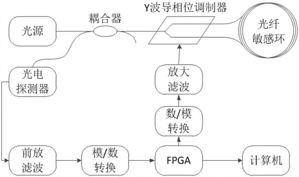
[0032] The present invention proposes a method for tracking and measuring the eigenfrequency of a fiber optic gyro Sagnac fiber ring. The overall structure of the measuring device used is as follows: figure 1shown. The device mainly includes light source, coupler, Y waveguide phase modulator, optical fiber sensitive ring, photodetector, preamplifier filter part, analog / digital conversion part, FPGA, digital / analog conversion part, drive amplifier filter circuit part, computer, etc. part.

[0033] The light emitted by the light source enters the Y waveguide phase modulator through the coupler. After being polarized in the Y waveguide phase modulator, the light is divided into two beams of linearly polarized light with equal intensity by the Y waveguide. One beam of linearly polarized light propagates clockwise along the fiber sensitive ring, and the ...


PUM


Abstract

The invention relates to an eigenfrequency tracking measurement method of a Sagnac optical fiber ring of an optical fiber gyroscope, and belongs to the technical field of fiber-optic gyroscopes. The eigenfrequency tracking measurement method comprises the following steps: after going through a coupler and a Y waveguide phase modulator, dividing light into two beams of linearly polarized light, respectively propagating the two beams of linearly polarized light clockwise and anticlockwise along an optical fiber sensing ring, performing sawtooth wave phase modulation and square wave bias phase modulation at the phase modulator and then returning to a Y waveguide position for interference; after processing, demodulating an error signal from an FPGA (field programmable gate array); and adjusting the frequency of a sawtooth wave modulation signal and the frequency of a square wave bias modulation signal according to the intensity of the error signal, wherein the frequency of the sawtooth wave signal is equal to the even number times of the eigenfrequency, and the error signal is zero, and at the moment, the square wave bias modulation frequency is accurately located on the eigenfrequency, the frequency of the sawtooth wave modulation signal is just the even number times of the eigenfrequency, and the square wave bias modulation frequency is equal to the eigenfrequency. According to the method, the purposes of tracking measurement for the eigenfrequency of the optical fiber gyroscope and adjustment of the square wave bias frequency onto the eigenfrequency are realized.

Description

technical field [0001] The invention belongs to the technical field of fiber optic gyroscopes, and in particular relates to a method for tracking and measuring the eigenfrequency of Sagnac fiber optic rings of fiber optic gyroscopes. Background technique [0002] Fiber optic gyro is an angular rate sensor based on the Sagnac effect. It has the advantages of small size, light weight, large dynamic range, and high sensitivity. It is used in military fields such as aviation, aerospace, navigation, and weapons, and civilian fields such as oil exploration. With the successful application of medium and low-precision fiber optic gyroscopes in recent years and the improvement of the performance of optical devices, the development of high-precision fiber optic gyroscopes for inertial navigation systems has become a development trend. [0003] Digital closed-loop fiber optic gyroscope is the main solution of medium and high-precision fiber optic gyroscope, and digital closed-loop fibe...

Claims


Application Information

Patent Timeline
Patent Type & Authority Applications(China)
IPC IPC(8): G01C25/00
CPCG01C25/005
Inventor 王夏霄于佳王翔郑月王婷婷马福杨苏凡
Owner 率为科技(北京)有限责任公司
Why Eureka
Try Eureka