Clearance evaluation method for highway aircraft runway

A technology for airstrips and runways, which is applied in special data processing applications, instruments, electrical digital data processing, etc., and can solve problems such as non-standard evaluation, error-prone evaluation, and unclear range of obstacle limitation surfaces.

Active Publication Date: 2017-11-24
AIR FORCE UNIV PLA
View PDF2 Cites 9 Cited by
  • Summary
  • Abstract
  • Description
  • Claims
  • Application Information

AI Technical Summary

Problems solved by technology

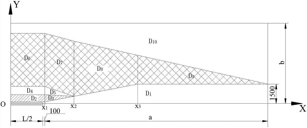
[0009] The purpose of the present invention is to provide a method for evaluating the clearance of highway runways, which solves the problems ...

Method used


Image

  • Clearance evaluation method for highway aircraft runway
  • Clearance evaluation method for highway aircraft runway
  • Clearance evaluation method for highway aircraft runway

Examples


Embodiment 1

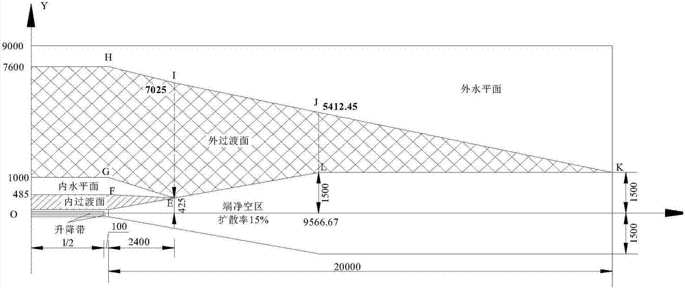
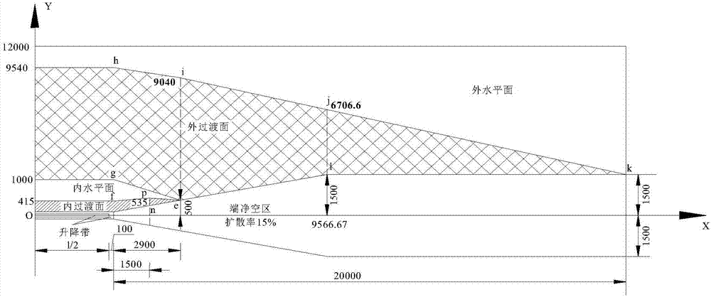
[0307] Example 1: It is known that the length of the airstrip of a third-level highway is 2600m, the road width is 40m, the east-west direction, the average longitudinal slope is 0, and the aforementioned highway airstrip coordinate system XOY is established. There are three obstacles. The road runway coordinates of the obstacles and the obstacle height are shown in Table 1.

[0308] Table 1 Obstacles in highway runway clearance area

[0309] Numbering

X(m)

Y(m)

Obstacle height h z (m)

1

2800

520

45

2

3550

650

56

3

8800

7400

360

[0310] 1. The horizontal distance from obstacle 1 to the end line of the lifting belt is:

[0311] d=2800-2600 / 2-100=1400m<1500m

[0312] And the vertical distance Y from the point to the center line of the runway 1 =520m>415m, it is preliminarily determined that the point is located between the inner transition surface and the inner horizontal plane. Use formula (1-3) to continue the judgment, the method is as follows:

[0313] Apply straight fp,

[0314]

[...


PUM


Abstract

The invention aims at providing a clearance evaluation method for a highway aircraft runway. The method comprises the steps of firstly, establishing a three-dimensional digital model of the clearance of the highway aircraft runway; converting geographical coordinates of an obstacle p into airport coordinates; determining which clearance limit surface of the highway runway the obstacle is located on; calculating the permission height of the obstacle; judging whether or not the obstacle is super high according to a transition surface model; obtaining a clearance evaluation conclusion. The clearance evaluation method for the highway aircraft runway has the advantages that whether or not the obstacle in a clearance area of the highway runway meets clearance requirements can be accurately judged, and the accuracy of the clearance evaluation of the highway runway is improved.

Description

Technical field [0001] The invention belongs to the technical field of highway runways, and relates to a method for evaluating the clearance of a highway airplane runway. Background technique [0002] The highway runway clearance area refers to the space area defined around the highway runway that limits the height of objects in order to ensure the safety of aircraft taking off, landing and go-around on the highway runway; [0003] In order to ensure the safety of the aircraft taking off and landing along the take-off and landing routes, there must be a good clearance condition around the airport, and the height of terrain and features in a certain area around the airport must be restricted. This limited area is called the airport clearance area. This restriction on the height of the terrain and features around the airport is called the airport clearance regulations (or specifications), also called the airport clearance requirements. Whether it is a permanent airport, a highway run...

Claims


Application Information

Patent Timeline
IPC IPC(8): G06F19/00
CPCG16Z99/00
Inventor 邵斌史保华许巍李光元江春林厉东
Owner AIR FORCE UNIV PLA
Why Eureka
Try Eureka