Power supply plug connection assembly

A technology of electric power supply and electric components, which is applied in the direction of electric components, parts of connecting devices, circuits, etc., can solve problems such as power outages of electrical facilities, electric shock accidents, unstable power supply connections, etc., and achieve increased use safety and simple operation Convenience and the effect of reducing electric shock accidents

Inactive Publication Date: 2017-11-24
俞灿
View PDF0 Cites 18 Cited by
  • Summary
  • Abstract
  • Description
  • Claims
  • Application Information

AI Technical Summary

Problems solved by technology

[0002] The power supply of electrical facilities is basically to directly insert the plug connected to it into the first power supply hole of the power supply socket, and the power supply socket and the mains connection will always be in the energized state, although the operation of this matching method is relatively simple and convenient. , but the lengths of the cables between the plug and the electrical equipment are different. After the plug is inserted into the first power supply hole, there is no other locking device to lock the plug. One of the power supply holes is detached, resulting in a sudden power failure of the electrical facilities, and in severe cases, it will directly cause damage to the electrical facilities. Therefore, the existing power supply connection between the plug and the first power supply hole is unstable. In addition, When the electrical equipment is not in use, the plug is often pulled out from the first power supply hole, which will cause the first power supply hole to be exposed. If there is a child in the family who directly inserts a finger or a metal rod into the first power supply hole, then It will cause electric shock accidents, and there is a greater potential safety hazard

Method used


Image

  • Power supply plug connection assembly
  • Power supply plug connection assembly
  • Power supply plug connection assembly

Examples


Embodiment Construction

[0018] The preferred embodiments of the present invention will be described in detail below in conjunction with the accompanying drawings, so that the advantages and features of the present invention can be more easily understood by those skilled in the art, so as to define the protection scope of the present invention more clearly.

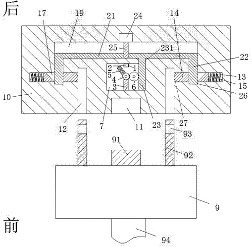
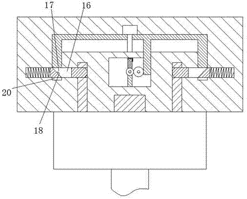
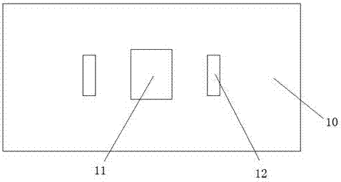
[0019] refer to Figure 1-3 The power supply plug-in assembly shown includes a power supply socket 10 embedded in the wall and a power connection part 9 for mating connection with the power supply socket 10. The middle of the rear end of the power connection part 9 is provided with The plug 91, the rear end of the power connection part 9 is respectively symmetrically provided with two plug boards 92 on the left and right sides of the plug 91, each of the plug boards 92 is provided with a locking groove 93 at the rear end, and the power supply socket A first power supply hole 11 is provided in the middle of the front end of the socket 10 to cooper...


PUM


Abstract

The invention discloses an electric power supply plug-in assembly, which comprises a power supply socket embedded in a wall and a power connection part for mating connection with the power supply socket. A plug is arranged in the middle of the rear end of the power connection part. The rear end of the power connection part is respectively symmetrically provided with two plug boards on the left and right sides of the plug, and each of the plug boards is provided with a locking groove at the rear end, and the front end of the power supply socket is provided in the middle to connect with the plug. The first power supply hole for matching connection, the front end of the power supply socket is respectively symmetrically provided with two slots for cooperating with the plug-in board on the left and right sides of the first power supply hole, and the outer side of each of the slots The end wall is provided with a lock column sliding groove. The overall structure of the present invention is simple, the power supply stability is good, the occurrence of electric shock accidents in the existing life is reduced, people's lives are effectively guaranteed, and the power-on and power-off of electrical facilities All are realized through the automatic control of the driving motor, and the operation is simple and convenient.

Description

technical field [0001] The invention relates to the field of electric power supply, in particular to an electric power supply plug assembly. Background technique [0002] The power supply of electrical facilities is basically to directly insert the plug connected to it into the first power supply hole of the power supply socket, and the power supply socket and the mains connection will always be in the energized state, although the operation of this matching method is relatively simple and convenient. , but the lengths of the cables between the plug and the electrical equipment are different. After the plug is inserted into the first power supply hole, there is no other locking device to lock the plug. One of the power supply holes is detached, resulting in a sudden power failure of the electrical facilities, and in severe cases, it will directly cause damage to the electrical facilities. Therefore, the existing power supply connection between the plug and the first power su...

Claims


Application Information

Patent Timeline
Patent Type & Authority Applications(China)
IPC IPC(8): H01R13/629H01R13/639H01R43/26
CPCH01R13/629H01R13/639H01R43/26
Inventor 俞灿
Owner 俞灿
Why Eureka
Try Eureka