
Camera testing device

A test device and camera technology, which is applied in image communication, television, electrical components, etc., can solve the problems that the shooting distance cannot be controlled and adjusted according to needs, the degree of automation is not high, and the performance of the camera cannot be accurately analyzed.

Active Publication Date: 2017-11-24
GOERTEK OPTICAL TECH CO LTD
View PDF5 Cites 3 Cited by
  • Summary
  • Abstract
  • Description
  • Claims
  • Application Information

AI Technical Summary

Problems solved by technology

[0003] However, when testing the camera at present, the shooting distance of the camera to the chart is fixed, and it is impossible to control and adjust the best shooting distance according to the needs.
Furthermore, the performance of the camera cannot be accurately analyzed, and the degree of automation of the equipment is not high

Method used


Image

  • Camera testing device
  • Camera testing device
  • Camera testing device

Examples


Embodiment Construction

[0054] Various exemplary embodiments of the present invention will now be described in detail with reference to the accompanying drawings. It should be noted that the relative arrangements of components and steps, numerical expressions and numerical values ​​set forth in these embodiments do not limit the scope of the present invention unless specifically stated otherwise.

[0055] The following description of at least one exemplary embodiment is merely illustrative in nature and in no way taken as limiting the invention, its application or uses.

[0056] Techniques, methods and devices known to those of ordinary skill in the relevant art may not be discussed in detail, but where appropriate, such techniques, methods and devices should be considered part of the description.

[0057] In all examples shown and discussed herein, any specific values ​​should be construed as exemplary only, and not as limitations. Therefore, other instances of the exemplary embodiment may have dif...


PUM


Abstract

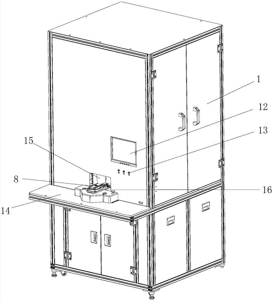
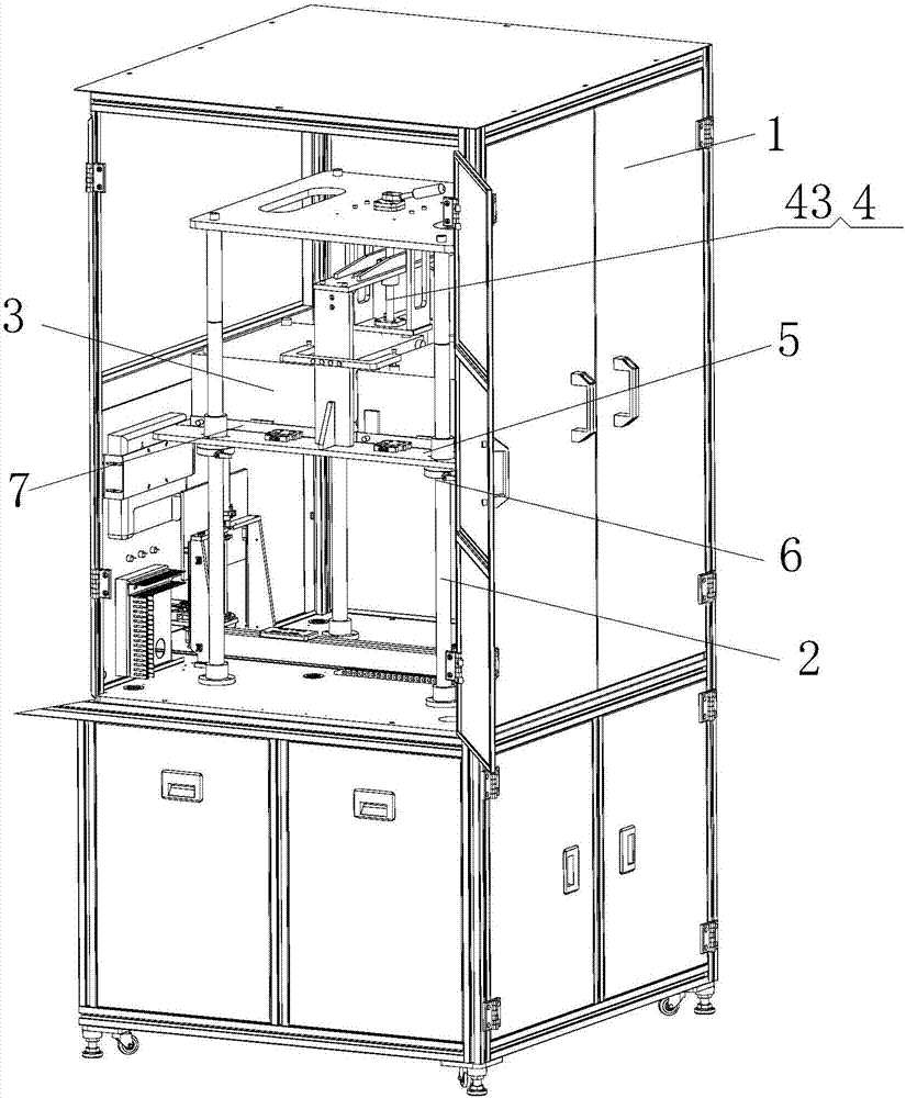
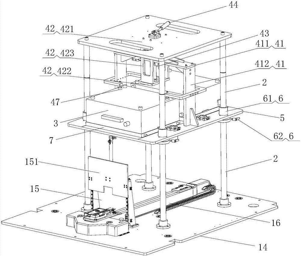
The invention discloses a camera testing device. The camera testing device comprises a closed box body (1), a bracket body (2), a graphic card set (7), a light box set (3) and an adjusting mechanism (4); the bracket body (2), the graphic card set (7), the light box set (3) and the adjusting mechanism (4) are arranged in the box body (1); the box body (1) is used for putting a camera body (8) therein; the graphic card set (7) is arranged at the bottom of the light box set (3); the light box set (3) is connected onto the bracket body (2) through a support plate (5); the camera body (8) is put below the support plate (5); and the adjusting mechanism (4) is arranged on the support plate (5), and drives the support plate (5) to slide corresponding to the bracket body (2), so that the support plate (5) moves towards or away from the camera body (8). By means of the camera testing device disclosed by the invention, the shooting distance between graphic card combination cameras can be automatically adjusted; furthermore, the best shooting distance can be selected flexibly and automatically; and thus, the shooting quality is improved.

Description

technical field [0001] The present invention relates to the detection of optical components, and more particularly, to a camera testing device. Background technique [0002] At present, photographic equipment and photographic electronic products are attracting the attention of the public, and various companies are constantly launching new products. While purchasing and using such products, users also have higher and higher requirements for equipment, especially the quality of cameras. Therefore, while companies need to improve the production quality of the camera, they also need to test and adjust the deviation of the camera during transportation and assembly. [0003] However, when testing the camera at present, the shooting distance of the camera to the chart is fixed, and it is impossible to control and adjust the best shooting distance as required. Furthermore, the performance of the camera cannot be accurately analyzed, and the degree of automation of the equipment is...

Claims


Application Information

Patent Timeline
IPC IPC(8): H04N17/00
CPCH04N17/002
Inventor 赵冬冬
Owner GOERTEK OPTICAL TECH CO LTD
Learn More