
Slicing and/or texturing for three-dimensional printing

a three-dimensional printing and slicing technology, applied in the direction of process and machine control, program control, instruments, etc., can solve the problems of customized solutions, complicated and long customized calculations, and the inability to manufacture the 3d model in its final form

Active Publication Date: 2016-01-21
STRATASYS LTD
View PDF2 Cites 31 Cited by
  • Summary
  • Abstract
  • Description
  • Claims
  • Application Information

AI Technical Summary

Benefits of technology

The present invention relates to a method and system for slicing a three-dimensional model of an object into a plurality of planar slices for printing using a 3D printer. The method involves identifying and manipulating volumes within the model, rather than calculating and defining individual pixels. The slicing process is carried out by identifying and marking regions of the model that belong to a support structure or are not part of the object. The method also involves obtaining texture maps and mapping them onto the slices to add texture to the model. The invention provides a faster and more efficient way to convert 3D models into print instructions for 3D printing.

Problems solved by technology

A 3D model cannot usually be manufactured in its final form, since each layer is molten when injected and usually has to be at least partially supported during its manufacture.
The calculations are typically carried out on the Central Processing Unit (CPU) part of the computer, or may use customized calculations on the GPU, or other graphics hardware, the customized calculations being complicated and lengthy.
However the graphics card is not used directly to produce the 3D printing instructions from the 3D model because the graphics card is designed to provide a 2D projection of a 3D image.
Hence, if the graphics card is to be used for 3D printing, it can only be through customized solutions.

Method used


Image

  • Slicing and/or texturing for three-dimensional printing
  • Slicing and/or texturing for three-dimensional printing
  • Slicing and/or texturing for three-dimensional printing

Examples


Embodiment Construction

[0036]The present invention, in some embodiments thereof, relates to a way of carrying out slicing for three dimensional printing and, more particularly, but not exclusively, to a way that is particularly suitable for carrying out on a graphics card.

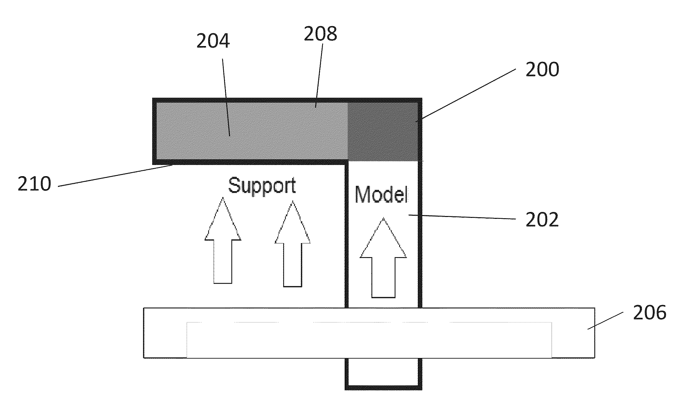
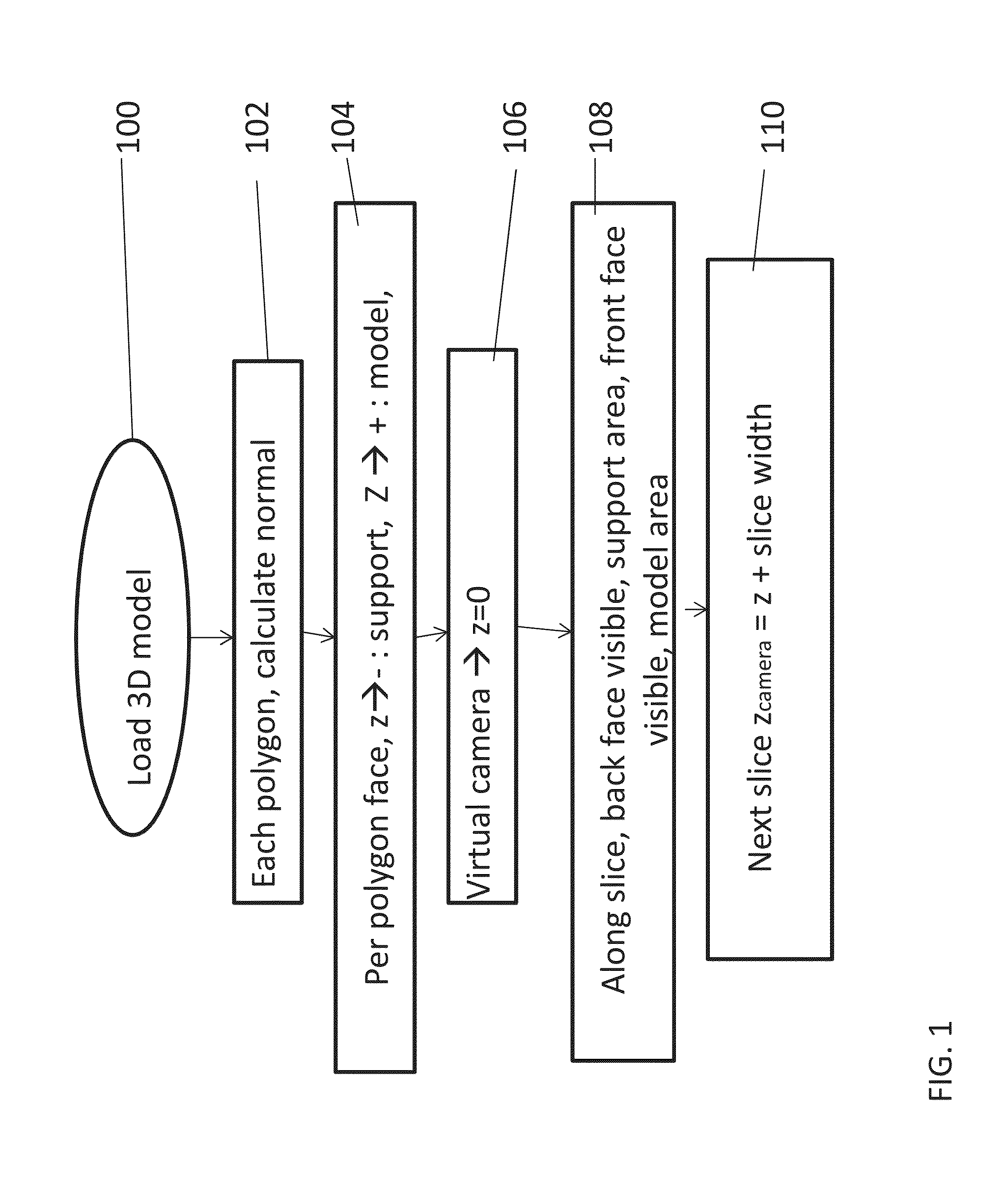
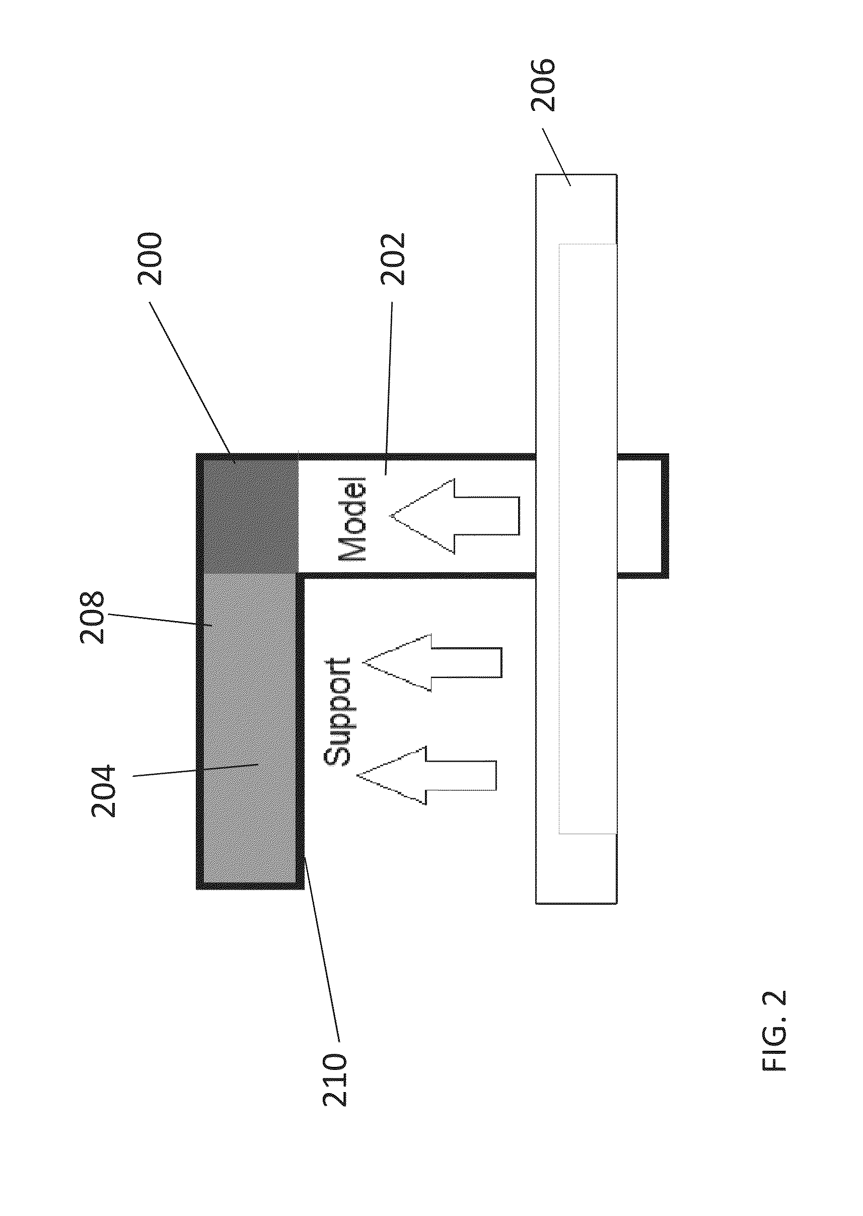
[0037]As will be explained in greater detail below, a method for slicing a three-dimensional model for printing of a corresponding object by a 3D printer, comprises: obtaining the envelope of the object as polygons, then for each region of a predefined work area within the slicing plane: identifying the closest polygon of the envelope that is positioned above the respective region; where no polygon is identified, then marking a corresponding region as a no-print region; if the direction vector of said closest above polygon has a positive component in the Z direction, then marking said corresponding region as a model region; and if the direction vector of said polygon has a negative component in the Z direction, then marking the region as...


PUM

PropertyMeasurementUnit
Areaaaaaaaaaaa
Surfaceaaaaaaaaaa
Distributionaaaaaaaaaa

Abstract

A method for slicing a three-dimensional model for printing of a corresponding object by a 3D printer, comprises: obtaining the envelope of the object as polygons, then for each region of a predefined work area within the slicing plane:identifying the closest polygon of said envelope that is positioned above said respective pixel; where no polygon is identified, then marking a corresponding region as a no-print region; if the direction vector of said closest above polygon has a positive component in the Z direction, then marking said corresponding region as a model region; and if the direction vector of said polygon has a negative component in the Z direction, then marking the region as a support region, and printing accordingly. An advantage of the above procedure is that the slicing, and in addition texture mapping, can be efficiently carried out on a graphics card or GPU.

Description

RELATED APPLICATION / S[0001]This application claims the benefit of priority under 35 USC §119(e) of U.S. Provisional Patent Application No. 61 / 782,142 filed Mar. 14, 2013, the contents of which are incorporated herein by reference in their entirety.FIELD AND BACKGROUND OF THE INVENTION[0002]The present invention, in some embodiments thereof, relates to a way of carrying out slicing for three dimensional printing and, more particularly, but not exclusively, to a way that is particularly suitable for being implemented on a graphics card or graphical processing unit (GPU).[0003]Three-dimensional (3D) inkjet printing in its broadest sense is a form of additive manufacture, in which any material that can be squeezed through an injection nozzle is applied in layers, in accordance with a plan or model, to form a three-dimensional object.[0004]The model may be obtained in any one of a number of ways, for example by carrying out 3D measurements of an original product that it is desired to cop...

Claims


Application Information

Patent Timeline
IPC IPC(8): G06F17/50B29C67/00
CPCG06F17/50B33Y10/00B33Y50/02B29C67/0088G05B19/4099G06T17/10G05B2219/49014G05B2219/49039B29C64/386G06F30/00
Inventor SHTILERMAN, STANISLAV
Owner STRATASYS LTD
Learn More