Novel water cup

A water cup and a new type of technology, applied in the field of water cups, can solve the problems of reduced service life of the cup body, unstable power supply connection, easy to cause electric shock accidents, etc., and achieve the effects of low production cost, safe and stable power supply, and avoidance of electric shock accidents.

Inactive Publication Date: 2017-12-01
戚天儿
View PDF0 Cites 0 Cited by
  • Summary
  • Abstract
  • Description
  • Claims
  • Application Information

AI Technical Summary

Problems solved by technology

[0002] The water cup is a commonly used utensil in people's daily life. With the continuous advancement of science and technology, the function of the water cup is not completely limited to the function of storing water, but also has the function of boiling water. When boiling water, the power transmission terminal needs to be inserted into the power transmission The power transmission terminal of the cup body can be directly inserted into the power supply hole of the power transmission frame to cooperate with the power supply. Although this plugging method is very convenient to operate, the length of the wire between the power transmission terminal and the cup body is different. , when in use, the wires are often placed randomly. If someone accidentally kicks and hits the wires by mistake, this will cause the power transmission terminal to be directly disconnected from the matching connection with the power supply hole of the power transmission frame, resulting in a sudden power failure of the cup. As a result, the service life of the cup is reduced, and if it is serious, it will directly cause the cup to be burned. Therefore, there is a potential safety hazard of unstable power supply connection in the existing power transmission terminal and power supply slot, and the existing power transmission Terminals are prone to electric shock accidents during plugging and unplugging

Method used


Image

  • Novel water cup
  • Novel water cup
  • Novel water cup

Examples


Embodiment Construction

[0022] The preferred embodiments of the present invention will be described in detail below in conjunction with the accompanying drawings, so that the advantages and features of the present invention can be more easily understood by those skilled in the art, so as to define the protection scope of the present invention more clearly.

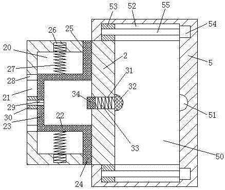
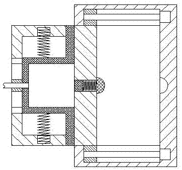
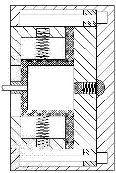
[0023] refer to Figure 1-7 A new type of water cup shown includes a power transmission frame 5 and a power transmission terminal 1 connected to the cup body 10 through a wire 11. The left end surface of the cup body 10 is equipped with an arm 12, and the right end surface is provided with a water outlet 13. The power transmission The frame 5 is provided with a sliding cavity 50 with the port facing left, and the sliding plate 2 can be smoothly arranged in the sliding cavity 50. The right end wall center of the sliding cavity 50 is provided with a power transmission groove 51, and the front and rear ends of the sliding cavity 50 are The wall is c...


PUM


Abstract

The invention discloses a new type of water cup, which includes a power transmission frame and a power transmission terminal connected to the cup body through wires. The left end of the cup is equipped with an arm and the right end is provided with a water outlet. In the left sliding cavity, slide plates can be smoothly arranged in the left and right sides of the sliding cavity, and a power transmission groove is set in the center of the right end wall of the sliding cavity, and a first sliding cavity is correspondingly set in the front and rear end walls of the sliding cavity, and the sliding plate The right sides of the front and rear end surfaces are correspondingly provided with protruding arms that are smoothly fitted and connected to the first sliding cavity, and each of the first sliding cavities is provided with a smooth piece for moving the protruding arms to the left and right. The present invention The overall structure is simple, the production cost is low, and the power supply is safe and stable, which effectively reduces the electric shock accidents in the existing life, and can also avoid the occurrence of power failure accidents caused by accidental kicking and bumping of the cup body, and the locking of the power transmission terminal is safe and reliable. The operation of the device is simple and convenient.

Description

technical field [0001] The invention relates to the field of water cups, in particular to a novel water cup. Background technique [0002] The water cup is a commonly used utensil in people's daily life. With the continuous advancement of science and technology, the function of the water cup is not completely limited to the function of storing water, but also has the function of boiling water. When boiling water, the power transmission terminal needs to be inserted into the power transmission The power transmission terminal of the cup body can be directly inserted into the power supply hole of the power transmission frame to cooperate with the power supply. Although this plugging method is very convenient to operate, the length of the wire between the power transmission terminal and the cup body is different. , when in use, the wires are often placed randomly. If someone accidentally kicks and hits the wires by mistake, this will cause the power transmission terminal to be d...

Claims


Application Information

Patent Timeline
IPC IPC(8): A47J27/21A47G19/22
CPCA47J27/21008A47G19/2288A47J27/21166
Inventor 戚天儿
Owner 戚天儿
Why Eureka
Try Eureka