Combine

A technology of combine harvesters and conveyors, which is applied in the directions of harvesters, cutters, agricultural machinery and implements, etc., can solve the problems of increasing the number of parts and complex structures, etc.

Inactive Publication Date: 2017-12-01
YANMAR POWER TECHNOLOGY CO LTD
View PDF7 Cites 3 Cited by
  • Summary
  • Abstract
  • Description
  • Claims
  • Application Information

AI Technical Summary

Problems solved by technology

However, this structure is complicated and has a problem of increasing the number of parts

Method used


Image

  • Combine
  • Combine
  • Combine

Examples


Embodiment Construction

[0055] First, the combine harvester 100 will be briefly described.

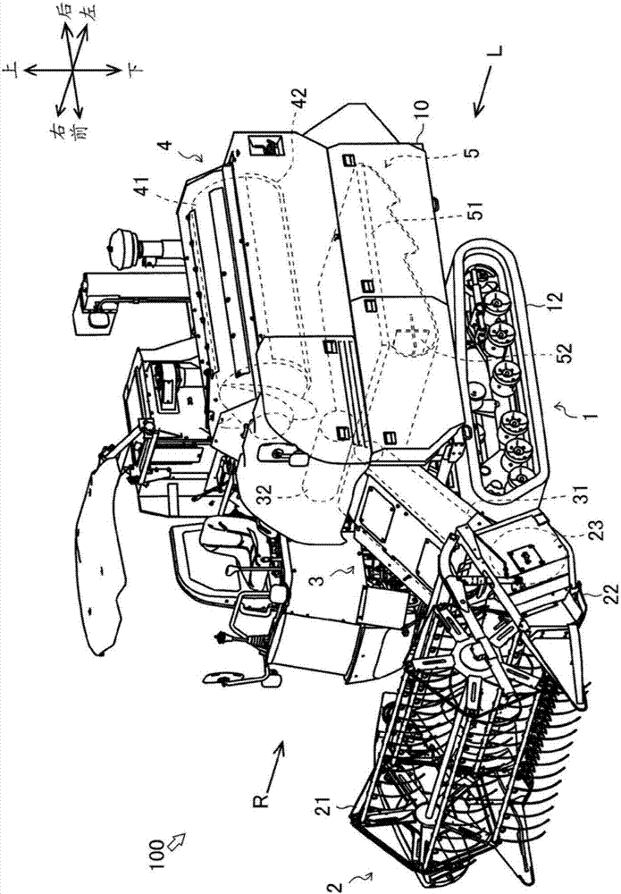
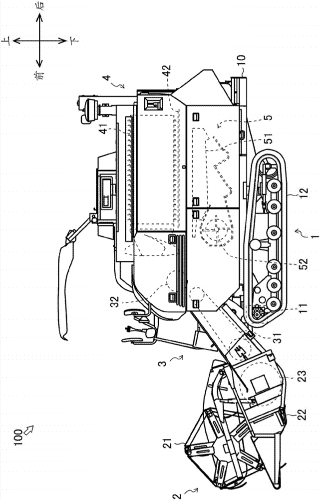
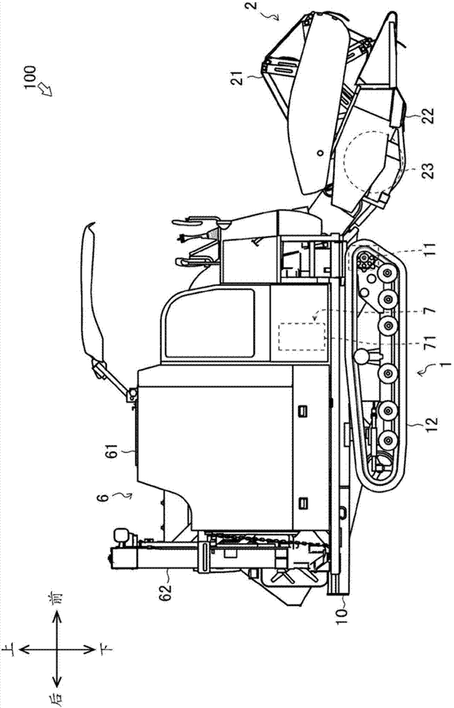
[0056] figure 1 A combine harvester 100 is given. figure 2 From figure 1 Arrow L to observe the resulting figure, image 3 From figure 1 The arrow R observed in the resulting figure. In addition, in the figure, the front-back direction, the left-right direction, and the up-down direction of the combine harvester 100 are shown.

[0057] The combine harvester 100 is mainly composed of a traveling device 1 , a harvesting device 2 , a conveying device 3 , a threshing device 4 , a screening device 5 , a storage device 6 , and a power device 7 .

[0058] The traveling device 1 is disposed below the chassis 10 . The travel device 1 is composed of a transmission 11 and crawler belt devices 12 , 12 . The transmission 11 transmits rotational power of an engine 71 to be described later to the crawler belt devices 12 , 12 . Crawler belt apparatuses 12 and 12 run the combine 100 in the front-back direction. More...


PUM


Abstract

This combine 100 is provided with: a reaping device 2 for reaping grain culms, a conveying device 3 for conveying the reaped grain culms, and a threshing device 4 for threshing the conveyed grain culms, the reaping device 2 and the conveying device 3 being capable of pivoting up and down, wherein, when the forward direction is the direction in which the conveying device 3 conveys the grain culms from the reaping device 2 to the threshing device 4, the conveying device 3 moves in the reverse direction by using the pivoting action of the conveying device 3 and the reaping device 2.

Description

technical field [0001] The present invention relates to combine harvesters. Background technique [0002] Conventionally, there is known a combine that reaps ear stalks while running, and threshes the harvested ear stalks (for example, refer to Patent Document 1). The combine harvester is equipped with a conveying device for conveying ear stalks from the harvesting device to the threshing device. The conveying device can move freely in the reverse direction under the condition that the ear stalk is blocked. However, such a structure is complicated and has a problem of increasing the number of components. [0003] However, the harvesting device can be freely raised and lowered (for example, refer to Patent Document 2). Specifically, the harvesting device and the conveying device can freely rotate up and down in an integrated state. This is to be able to adjust the cutting height according to the ear stalk or to be able to perform a smooth rotation. Therefore, there is a ...

Claims


Application Information

Patent Timeline
IPC IPC(8): A01D61/00A01D41/12
CPCA01D41/12A01D61/00A01D41/14A01D61/02Y02P60/00
Inventor 和田俊郎洼田昭彦阿部大介
Owner YANMAR POWER TECHNOLOGY CO LTD
Why Eureka
Try Eureka