
Surgical clamps

A clamping and clamping technology, which is applied in the direction of surgery, medical science, external fixator, etc., can solve the problems of damaged rods, increased complexity, etc.

Active Publication Date: 2017-12-01
BIOMET MFG CORP
View PDF6 Cites 3 Cited by
  • Summary
  • Abstract
  • Description
  • Claims
  • Application Information

AI Technical Summary

Problems solved by technology

Additional tools can add complexity
Additionally, conventional clamps can damage rods, pins, and wires due to overtightening of the threaded mechanism

Method used


Image

  • Surgical clamps
  • Surgical clamps
  • Surgical clamps

Examples


Embodiment Construction

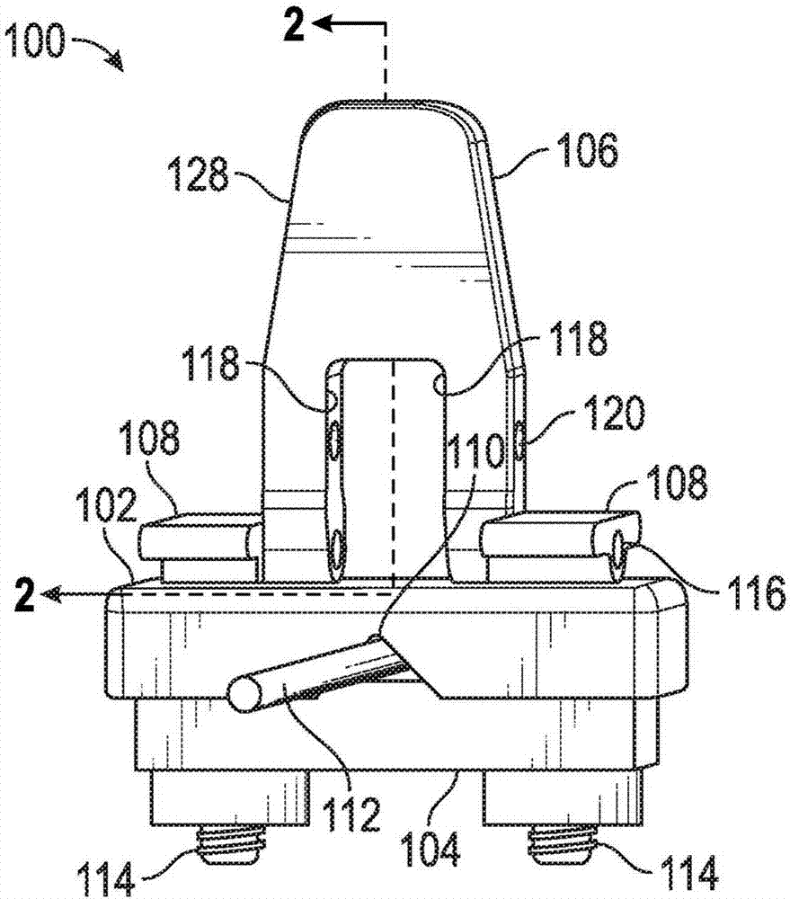
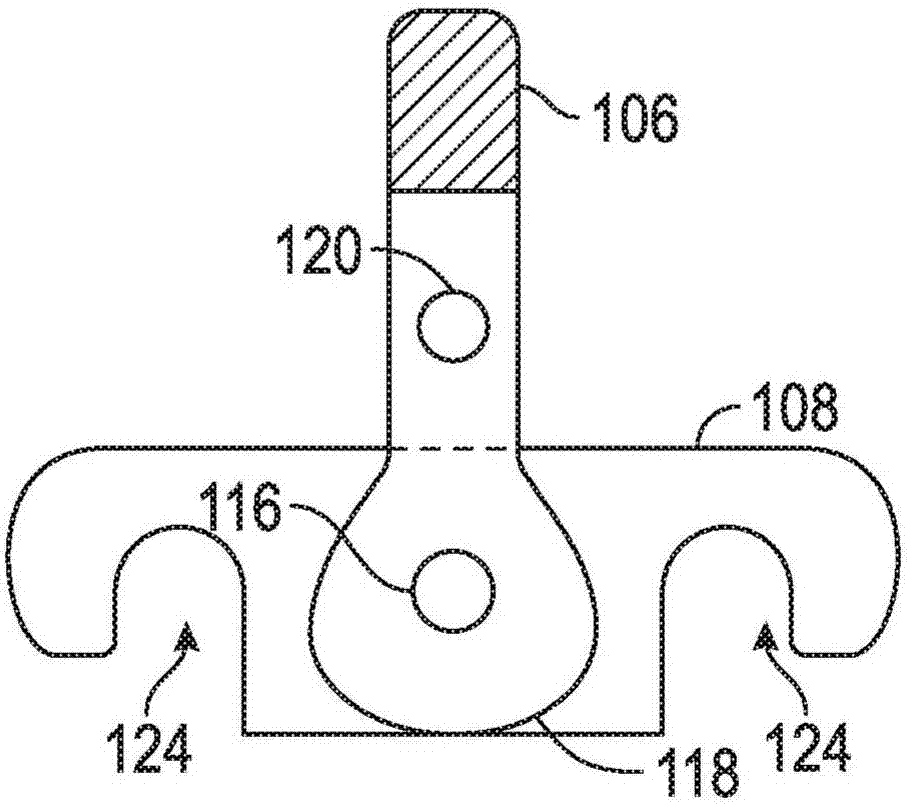
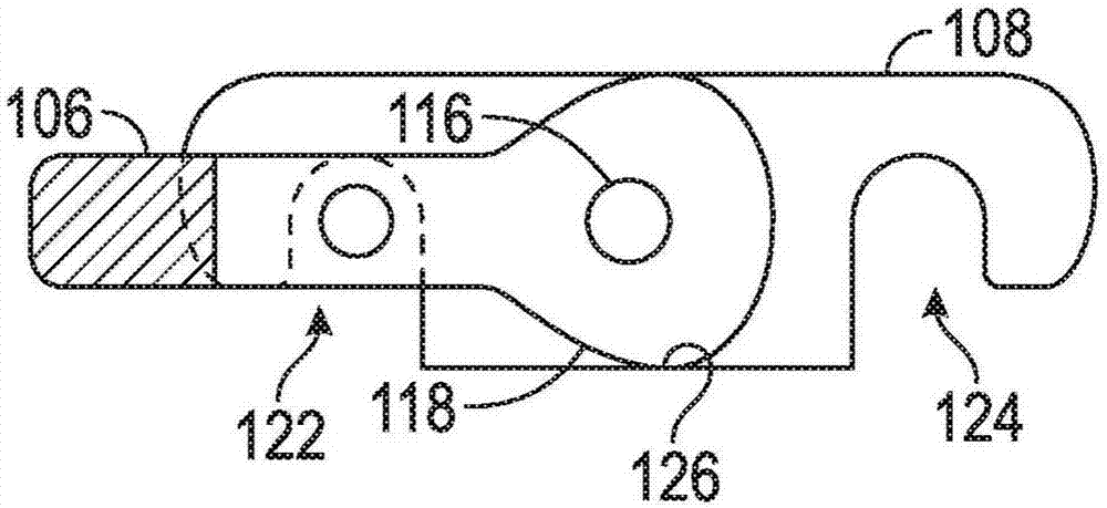
[0043] During and after a surgical procedure, various rods, pins and wires may need to be clamped into place. As disclosed herein, a clamp may utilize a camming portion to clamp or otherwise restrain a rod, pin, or wire by a clamping member (sometimes referred to as a jaw or clamping surface). In addition, the camming portion may be used to clamp the clamping member to a fixture, such as a support, which is used in a realignment procedure or to support a bone or bone after a compound fracture. other limbs.

[0044]The clamps disclosed herein may utilize a cam to lock the element in place. For example, the operating lever may pivot from the first position to the second position after the lever is placed adjacent to the support structure. During the pivoting action, the camming may cause the clamping surfaces of the clamp to come together and grip the rod, pin, wire or support structure.

[0045] As disclosed herein, the locking pin in combination with the locking hole and re...


PUM


Abstract

The present disclosure provides a clamp. The clamp can include a first clamp member, a second clamp member, and a lever. The first clamp member can include a first gripping surface. The second clamp member can include a second gripping surface. The lever can be connected to the first clamp member and can define a cam located proximate the first clamp member. The lever can be pivotable between a first position and a second position. A transition from the first position to the second position can cause the cam to move the second clamp member towards the first clamp member.

Description

technical field [0001] The present invention relates to surgical instruments. More specifically, the present invention relates to surgical clips that can be used during and after surgical procedures. Background technique [0002] Traditional surgical clamps employ a threaded mechanism that may require the use of a wrench or other tool to tighten the clamp. Additional tools can add to the complexity. Additionally, conventional clamps can damage rods, pins, and wires due to overtightening of the threaded mechanism. Contents of the invention [0003] To better illustrate the clamps disclosed herein, a non-limiting list of examples is provided here: [0004] In Example 1, a clamp may include a first clamping member, a second clamping member, and an operating lever. The first clamping member may comprise a first clamping surface. The second clamping member may comprise a second clamping surface. The operating lever may be connected to the first clamping member. The lever...

Claims


Application Information

Patent Timeline
IPC IPC(8): A61B17/60A61B17/64
CPCA61B17/60A61B17/645A61B17/6458A61B17/6466
Inventor P·T·斯莱格尔
Owner BIOMET MFG CORP
Learn More