
Backlight control method, backlight control device and display equipment

A technology of backlight control and backlight brightness, applied in static indicators, instruments, etc., can solve the problems of limited viewing experience, no improvement in static contrast, visual fatigue, etc., and achieve the effect of avoiding visual damage.

Inactive Publication Date: 2017-12-05
WHALEY TECH CO LTD
View PDF6 Cites 4 Cited by
  • Summary
  • Abstract
  • Description
  • Claims
  • Application Information

AI Technical Summary

Problems solved by technology

[0004] (1) For the non-local dimming (local dimming) dynamic backlight method, in darker scenes, the brightness of the backlight will be reduced accordingly, which may cause the details of dark scenes to be blurred
[0005] (2) In a brighter scene, the backlight may reach its maximum value, and in a darker environment, it will feel dazzling
[0006] (3) The non-local dimming dimming mode results in the same sub-screen, the brightness of the backlight is always the same everywhere in the screen, and the static contrast does not improve
The overall improved viewing experience is limited
[0007] (4) Considering the imaging mode and principle of the human eye, frequent brightness changes can easily cause visual fatigue and damage vision

Method used


Image

  • Backlight control method, backlight control device and display equipment
  • Backlight control method, backlight control device and display equipment
  • Backlight control method, backlight control device and display equipment

Examples


example 1

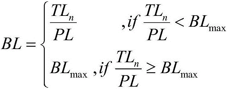
[0070] Determine the control target value BL of the backlight brightness according to the following formula:

[0071]

[0072] where, BL max Indicates the maximum backlight brightness that the display device can achieve, TL n Indicates the constant value under the current nth environmental condition, and PL indicates the current picture pixel brightness.

example 2

[0074] Determine the control target value BL of the backlight brightness according to the following formula:

[0075]

[0076] where, BL max Indicates the maximum backlight brightness that the display device can achieve, TL n Indicates the constant value under the current nth environmental condition, and PL indicates the current picture pixel brightness.

example 3

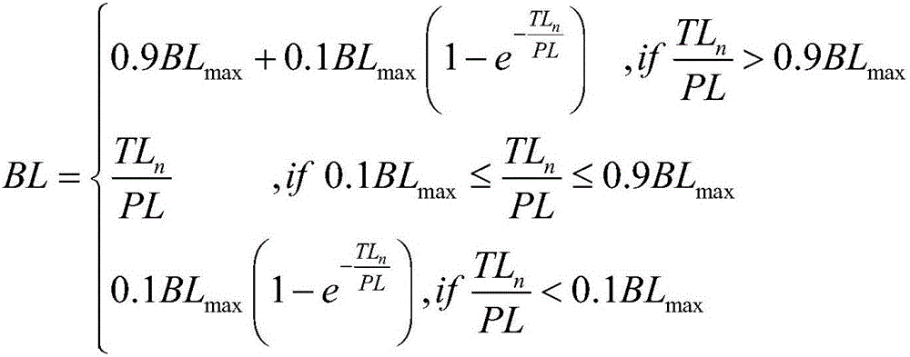
[0078] Determine the control target value BL of the backlight brightness according to the following formula:

[0079]

[0080] where, BL max Indicates the maximum backlight brightness that the display device can achieve, TL n Indicates the constant value under the current nth environmental condition, and PL indicates the current picture pixel brightness.

[0081] After modifying formula (3) in the form of a piecewise function or / and an approximation function, the actual perceived brightness of the human eye (that is, the product of the screen pixel brightness and the backlight brightness) is not always equal to TL, but it can be guaranteed that in The fluctuation near TL avoids the phenomenon that the brightness of the overall output of the TV changes greatly. While avoiding the impact of the viewing experience during the occurrence stage, it also retains the effect of eye protection to a large extent.


PUM


Abstract

The invention discloses a backlight control method, which belongs to the technical field of display. A mode of a product of picture pixel brightness and backlight brightness is firstly put forward to measure the received integrated brightness when a person watches a display picture, the phenomenon that the product is basically constant in a certain environment condition is used as a control target, the backlight brightness is dynamically controlled according to the current picture pixel brightness, visual impairment resulting from frequent changes in the actually-received brightness of the human eye can be avoided, and the purpose of protecting the eyes is further achieved. The invention also discloses a backlight control device and display equipment. In comparison with the prior art, visual impairment resulting from frequent changes in the actually-received brightness of the human eye can be avoided, and the purpose of protecting the eyes is further achieved; and besides, the algorithm is simple, requirements on hardware of the equipment are low, and realization on various existing display equipment is facilitated.

Description

technical field [0001] The invention relates to a backlight control method, in particular to a non-local dimming (local dimming) backlight control method and device, and belongs to the field of display technology. Background technique [0002] As one of the cores of display technology, backlight control technology has always been valued by researchers. At present, dynamic backlight adjustment technology has been widely used in various display devices. The so-called dynamic backlight adjustment refers to real-time control of the brightness of the backlight source to achieve a certain control target. According to different control objectives or control methods, a variety of backlight control technologies have emerged. From the perspective of control objectives, some are aimed at improving display contrast or reducing energy consumption, some are aimed at improving user viewing comfort, and others are based on Vision protection is the goal. In terms of control methods, some ...

Claims


Application Information

Patent Timeline
Patent Type & Authority Applications(China)
IPC IPC(8): G09G3/34
Inventor 李中源徐婉利
Owner WHALEY TECH CO LTD
Learn More