
Blind spot detection systems and methods

A detection system and blind spot technology, applied in the field of vehicle systems, can solve problems such as not recognizing other vehicles

Inactive Publication Date: 2017-12-19
FORD GLOBAL TECH LLC
View PDF0 Cites 10 Cited by
  • Summary
  • Abstract
  • Description
  • Claims
  • Application Information

AI Technical Summary

Problems solved by technology

Existing systems allow a vehicle to detect its own blind spots, but not those of other vehicles

Method used


Image

  • Blind spot detection systems and methods
  • Blind spot detection systems and methods
  • Blind spot detection systems and methods

Examples


Embodiment Construction

[0082] In the following disclosure, reference is made to the accompanying drawings which form a part hereof, and in which is shown by way of illustration specific embodiments in which the invention may be practiced. It is to be understood that other embodiments may be utilized and structural changes may be made without departing from the scope of the present invention. References in the specification to "one embodiment," "an embodiment," "example embodiment," etc. indicate that the described embodiment may include a particular feature, structure, or characteristic, but that each embodiment may not necessarily include the particular feature, structure, or structure. or features. Moreover, such terms are not necessarily referring to the same embodiment. Further, when a specific feature, structure or characteristic is described in relation to an embodiment, it is claimed that, whether or not explicitly described, it is within the ability of those skilled in the art to affect the...


PUM


Abstract

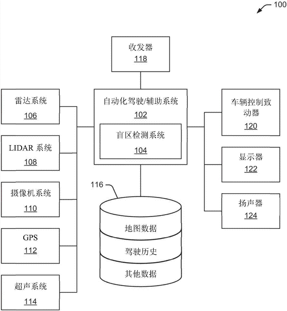
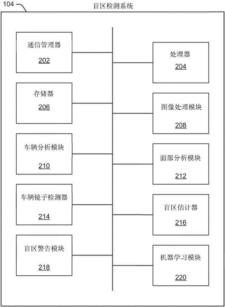
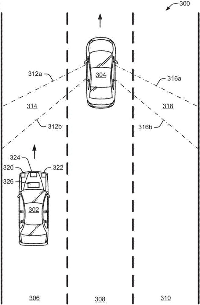
Example blind spot detection systems and methods are described. In one implementation, a primary vehicle detects a secondary vehicle ahead of the primary vehicle in an adjacent lane of traffic. A method determines dimensions of the secondary vehicle and estimates a vehicle class associated with the secondary vehicle based on the dimensions of the secondary vehicle. The method also identifies a side-view mirror location on the secondary vehicle and determines a blind spot associated with the secondary vehicle based on the vehicle class and the side-view mirror location.

Description

technical field [0001] The present invention relates to vehicle systems, and more particularly, to systems and methods for detecting blind spots of nearby vehicles. Background technique [0002] Motor vehicles and other vehicles provide a significant portion of transportation for commercial, governmental, and private entities. In areas of heavy vehicular traffic or limited visibility, it is important to know the location of the blind spots of surrounding vehicles. By detecting the blind spots of surrounding vehicles, the host vehicle can adjust its driving activity to avoid or minimize the time spent driving through another vehicle's blind spots. Existing systems allow a vehicle to detect its own blind spots, but do not identify the blind spots of other vehicles. [0003] Various vehicles on a typical road not only have different driver positions relative to the vehicle's side mirrors and windows, but also have different sizes and shapes. Additionally, different vehicles ...

Claims


Application Information

Patent Timeline
IPC IPC(8): B60W50/00B60W50/14
CPCB60W50/0098B60W50/14B60W2050/143B60W30/09B60W30/0956G08G1/167B60W2420/54B60R2300/8026G08G1/166B60K31/0008B60K2031/0025G01S2013/9315B60W2554/00B60W2420/403B60W2420/408B60W30/08B60R2300/80
Inventor 哈珀丽特辛格·班瓦伊特吉内什·J·杰恩
Owner FORD GLOBAL TECH LLC
Learn More