Low-air-pressure excited Raman light source system apparatus

A technology of stimulated Raman, light source system, applied in gas laser parts, lasers, laser parts and other directions, can solve the problems of large influence, poor laser stability, limited service cycle of Raman tubes, etc., to improve the effective Effectiveness of life cycle, improved stability, improved safety

Inactive Publication Date: 2017-12-19
安徽科创中光科技股份有限公司
View PDF5 Cites 2 Cited by
  • Summary
  • Abstract
  • Description
  • Claims
  • Application Information

AI Technical Summary

Problems solved by technology

[0004] Among them, the device that generates multi-wavelength stimulated Raman light can emit multi-wavelength light beams. Since the air pressure in the Raman tube is set in advance, the stability of the laser is poor and it is greatly affected by the measurement environment, and Impurities in the optical path gas cannot be removed, resulting in a limited lifespan of the Raman tube

Method used


Image

  • Low-air-pressure excited Raman light source system apparatus
  • Low-air-pressure excited Raman light source system apparatus

Examples


Embodiment

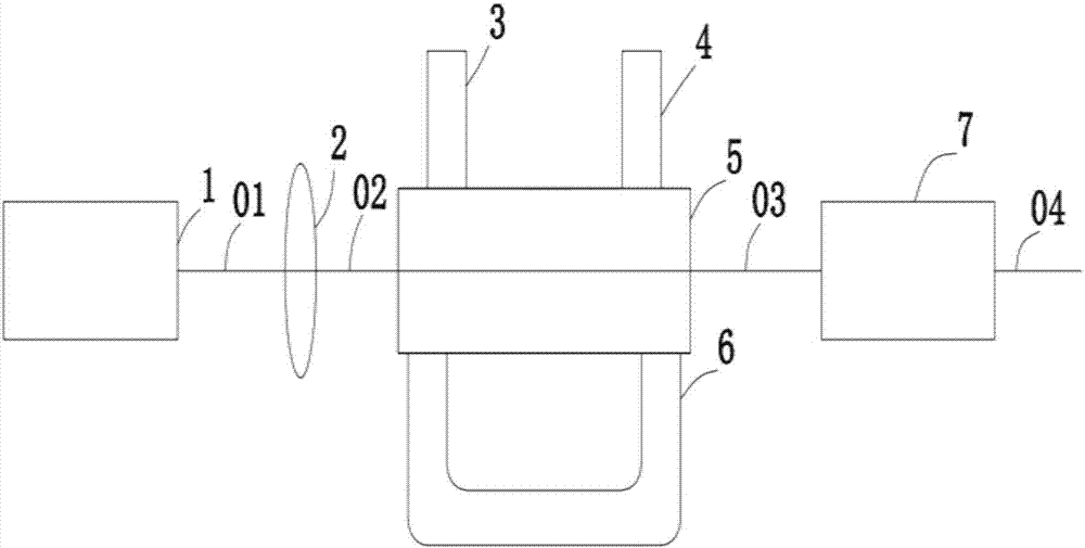
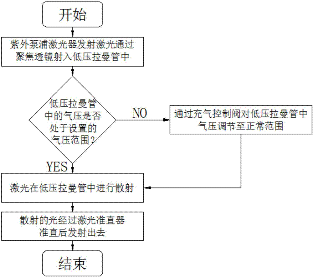
[0022] Such as figure 1 with figure 2 As shown, the low-pressure stimulated Raman light source system device includes: ultraviolet pumping laser 1, focusing lens 2, intelligent air pressure sensing device 3, inflation control valve 4, low-pressure Raman tube 5, impurity filtering device 6 and laser Collimator 7.

[0023] Wherein, after the ultraviolet pumping laser 1 is turned on, the ultraviolet pumping laser 1 emits light 1 01 which is focused by the focusing lens 2 into light 2 02 and injected into the low-pressure Raman tube 5 .

[0024] The air pressure in the low-pressure Raman tube 5 is detected in real time by the air pressure sensing device 3. When the air pressure is not within the normal working range, the air pressure sensing device 3 sends an electrical signal instruction to control the inflation control valve 4 to input positive pressure into the low-pressure Raman tube 5. Air pressure or negative air pressure, so that the air pressure in the low-pressure Rama...


PUM


Abstract

The invention discloses a low-air-pressure excited Raman light source system apparatus. The apparatus comprises an ultraviolet pumping laser, a focusing lens, an intelligent air pressure sensing apparatus, an inflating control valve, a low-pressure Raman tube, an impurity filtering apparatus and a laser collimator, wherein the ultraviolet pumping laser emits laser to pass through the focusing lens to be focused into the low-pressure Raman tube and to finally emit to the laser collimator, wherein the low-pressure Raman tube is provided with the intelligent air pressure sensing apparatus for monitoring the air pressure in the low-pressure Raman tube, the inflating control valve used for supplementing air pressure and the impurity filtering apparatus used for removing impurities from air; and the intelligent air pressure sensing apparatus is electrically connected with the inflating control valve. By adoption of low-air-pressure design, the safety of the Raman tube apparatus can be improved; by virtue of design of the intelligent air pressure sensing apparatus and the inflating control valve, constant air pressure in the Raman tube can be ensured, and laser energy stability can be improved; and by virtue of the impurity filtering apparatus, the effective service cycle of the Raman tube is prolonged.

Description

technical field [0001] The invention relates to the technical field of Raman light sources, in particular to a low-pressure stimulated Raman light source system device. Background technique [0002] Raman spectroscopy technology can detect and analyze the composition of substances at the molecular level. It has the advantages of directness, non-destructiveness, and rapidity. This technology has been widely used in commodity inspection, industrial environmental protection, chemistry, biomedicine and other fields. It is an important research direction in the relevant scientific and technological circles. [0003] Chinese Invention Patent Publication No. CN103185712A provides a device for generating multi-wavelength stimulated Raman light. Its core technology is as follows. It consists of a laser and a focusing lens on its output optical path, a Raman tube and collimation components, especially the laser and A frequency multiplier is placed on the optical path between the focu...

Claims


Application Information

Patent Timeline
Patent Type & Authority Applications(China)
IPC IPC(8): H01S3/03H01S3/036H01S3/30
CPCH01S3/03H01S3/036H01S3/305
Inventor 汪思保
Owner 安徽科创中光科技股份有限公司
Why Eureka
Try Eureka