Non-contact induction current collection box

A non-contact, electrical box technology, applied in the field of collector boxes, achieves the effects of safe use, cost saving and easy installation

Pending Publication Date: 2018-01-09
许保康
View PDF0 Cites 1 Cited by
  • Summary
  • Abstract
  • Description
  • Claims
  • Application Information

AI Technical Summary

Problems solved by technology

[0003] The technical problem to be solved by the present invention is: in order to overcome the above-mentioned problems, we have designed this automatic electrified production line for products, which can not only provide power to the tooling board, but also be safe to use, easy to install, and not easy to cause electric shock accidents. Non-contact induction collector box

Method used


Image

  • Non-contact induction current collection box
  • Non-contact induction current collection box
  • Non-contact induction current collection box

Examples


Embodiment Construction

[0020] The present invention is described in further detail now in conjunction with accompanying drawing. These drawings are all simplified schematic diagrams, which only illustrate the basic structure of the present invention in a schematic manner, so they only show the configurations related to the present invention.

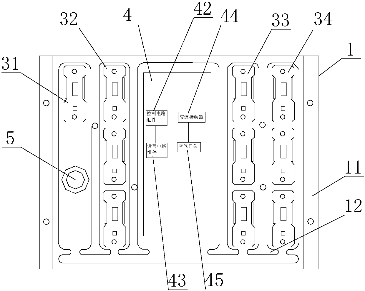
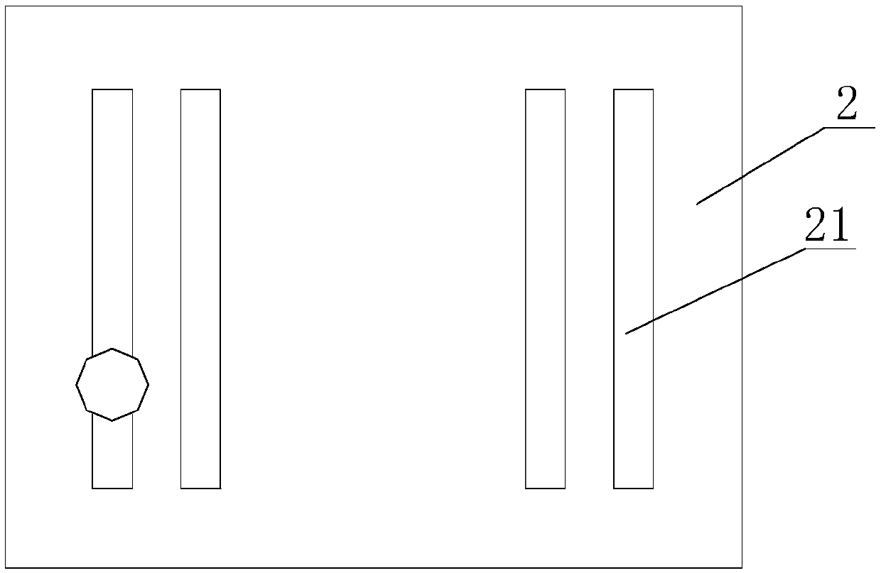
[0021] Such as figure 1 and figure 2 The non-contact induction collector box shown is used to provide power to the tooling board 6, and includes a box body 1 made of insulating material. The box body 1 consists of an outer frame body 11 and four T-shaped partitions connected in the outer frame body 11 Composed of 12, four T-shaped partitions 12 and the outer frame 11 form five accommodating cavities, the first conductive wheel set 31, the second conductive wheel set 32, the circuit control system 4, and the third conductive wheel set 33 And the fourth conductive wheel 34 groups are respectively located in the five accommodating cavities, the power-on indica...


PUM


Abstract

The invention relates to a non-contact induction collector box, which comprises a box body of insulating material, a box cover covered on the box body, a conductive wheel set installed in the box body, and a circuit control system. The circuit control system includes a The tag chip on it, at least one control circuit component, at least one read-write circuit component and AC contactor, and the air switch connected to the AC phase line, the air switch is connected to the AC contactor phase line, and the AC contactor is respectively connected to the second conductive wheel group, the third conductive wheel group, the fourth conductive wheel group, and the control circuit assembly are connected with each other, the control circuit assembly is connected with the read-write circuit assembly, and the read-write circuit assembly is connected with the tag chip through a non-contact induction signal. The non-contact induction collector box of the present invention can not only provide power to the tooling board, but also is safe to use, easy to install, and less likely to cause electric shock accidents.

Description

technical field [0001] The invention relates to the field of collector boxes, in particular to a non-contact induction collector box. Background technique [0002] The products in the automated production line are especially household appliances or electronic products, which must be operated with electricity during assembly, debugging, and aging testing. The commonly used measures are: install collector rails on the transmission device, generally 4 collector rails, the collector rails contain multiple conductive wheels, the conductive wheels are charged after the collector rails are connected to the power supply, and the products are placed on the tooling board Above, the metal conductive strip at the bottom of the tooling plate contacts the wheel body of the conductive wheel to electrify the tooling plate, and then provide power for the product. However, this form of collector rail is installed on the entire production line without any protective measures. After the power ...

Claims


Application Information

Patent Timeline
Patent Type & Authority Applications(China)
IPC IPC(8): H01R25/16H01R13/66H01R13/70H01R13/717
Inventor 许保康
Owner 许保康
Why Eureka
Try Eureka