An intelligent downhole wax removal and prevention device

A wax removal and smart well technology, applied in isolation devices, cleaning tools, boreholes/well components, etc., can solve the problems of different wax deposition speeds, many failures of well flushing valves, and simulation calculation thickness errors, etc., to improve cleaning efficiency. Wax cycle, wax removal efficiency is high

Inactive Publication Date: 2020-01-21
YANAN UNIV
View PDF6 Cites 0 Cited by
  • Summary
  • Abstract
  • Description
  • Claims
  • Application Information

AI Technical Summary

Problems solved by technology

Mechanical wax removal is to use mechanical means to scrape wax when the wax deposition reaches a certain level, but this method cannot remove the wax on the sucker rod joint and limiter, and it needs to be supplemented by other wax removal methods regularly; hot washing Wax removal has disadvantages such as low heat utilization rate and many failures of well flushing valves; electric-heated sucker rods have high energy consumption for wax removal, and the requirements for hollow sucker rods are particularly strict; although downhole microwave energy consumption is low, continuous heating will damage downhole Equipment; chemical paraffin removal on the well, resulting in the inability of the chemical to act on the wax deposition site in time
Existing wax removal and prevention devices mostly use a single wax removal and prevention technology, and different oil wells have different wax contents and wax deposition speeds. Using a single wax removal and prevention technology will lead to high energy consumption, low efficiency, and troublesome operation. Focus on prevention and combine prevention with prevention
The traditional wax removal and anti-wax technology is to infer the downhole wax deposition situation through the load of the pumping unit at the wellhead, but the downhole wax deposition situation often has an error with the simulated calculation thickness of the wellhead, resulting in unnecessary waste of energy or wax removal and anti-wax agents

Method used


Image

  • An intelligent downhole wax removal and prevention device
  • An intelligent downhole wax removal and prevention device
  • An intelligent downhole wax removal and prevention device

Examples


Embodiment Construction

[0020] The present invention will be described in detail below in conjunction with the accompanying drawings and specific embodiments.

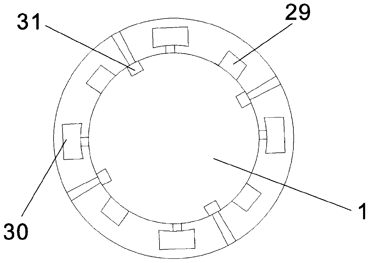
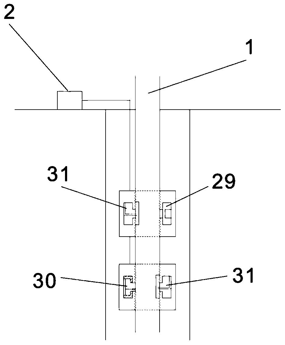
[0021] The present invention is an intelligent downhole wax removal and prevention device, the structure of which is as follows figure 1 and figure 2 As shown, it includes the following three modules that are evenly distributed on the outer wall of the oil pipe 1: a strong magnetic anti-wax module 29, a microwave heating wax removal module 30 and a chemical anti-wax removal module 31. The above three modules are all connected to the ground control box 2 located on the well. connect.

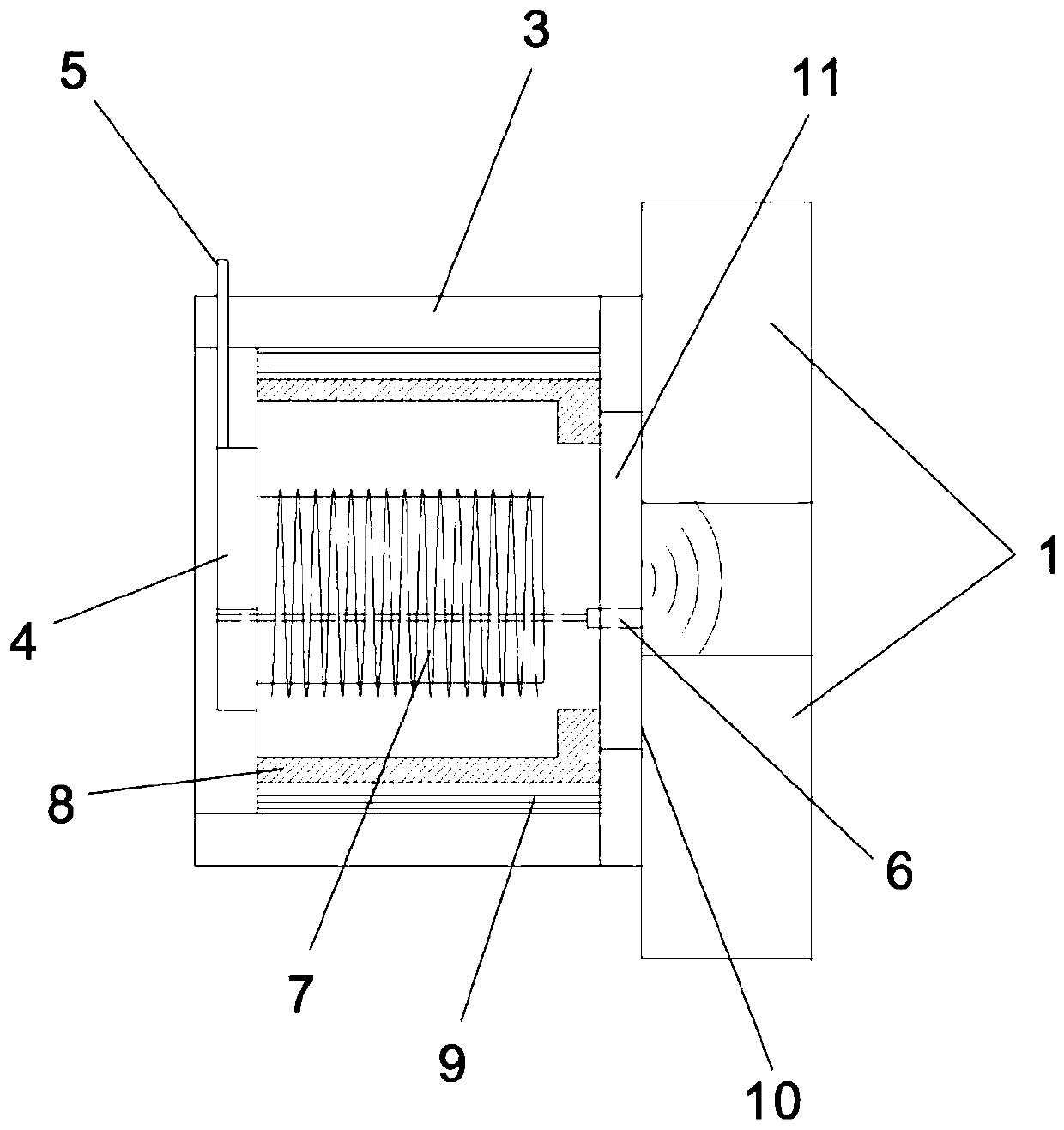
[0022] Such as image 3 As shown, the strong magnetic anti-wax module 29 includes a first airtight protective shell 3, the first airtight protective shell 3 is provided with a first control switch 4, and the first control switch 4 is respectively connected with a first cable 5 and a radiation thickness sensor 6, The first cable 5 passes through the first air...


PUM


Abstract

The invention discloses an intelligent downhole wax removing and preventing device. The intelligent downhole wax removing and preventing device comprises three modules evenly distributed on the outerwall of an oil pipe, wherein the three modules are the high-intensity magnetic wax preventing module, the microwave heating wax removing module and the chemical wax preventing and removing module. Theabove three modules are connected with a ground control box on a well. The intelligent downhole wax removing and preventing device is mainly to prevent wax and combined with a wax rremoving and preventing technology, and downhole conditions are identified quickly by using a radiation thickness sensor and a temperature sensor; downhole heating is conducted by using a magnetron to emit microwave, and wax removing is achieved by a controllable capillary dosing technology; wax removing period is improved by using high-intensity magnetic wax preventing, coupling between the oil pipes can be replaced with the whole device of the modules; moreover, the intelligent downhole wax removing and preventing device does not need to be stopped to be produced, the downhole wax deposition situation can beintelligently identified, the corresponding modules are opened, and the wax removing efficiency is high.

Description

technical field [0001] The invention belongs to the technical field of petroleum exploitation, and relates to an intelligent downhole wax removal and prevention device. Background technique [0002] In the process of oil extraction, as the wellbore fluid column rises, the temperature and pressure gradually decrease, and the paraffin dissolved in the oil crystallizes out, grows up and aggregates, and deposits on the solid surface such as the pipe wall, resulting in wax deposition Phenomenon. Downhole wax deposition will reduce the diameter of the tubing, increase the outer diameter of the sucker rod, increase the oil flow resistance, increase the loss along the tubing, and reduce the production of the oil well. Eccentric wear, at the same time, will increase the suspension point load in the upstroke; the suspension point load in the downstroke will decrease, causing an increase in alternating load and affecting the working life of the sucker rod; when the wax deposition is s...

Claims


Application Information

Patent Timeline
Patent Type & Authority Patents(China)
IPC IPC(8): E21B37/00E21B37/06E21B36/04
Inventor 吴小斌袁海博石小磊
Owner YANAN UNIV
Why Eureka
Try Eureka