Sewing machine and control method thereof

A technology of sewing machine and control unit, which is applied in the direction of sewing machine components, sewing equipment, cloth pressing mechanism, etc., and can solve problems such as damage to cloth and increased force applied to cloth

Inactive Publication Date: 2018-02-06
BROTHER KOGYO KK
View PDF5 Cites 3 Cited by
  • Summary
  • Abstract
  • Description
  • Claims
  • Application Information

AI Technical Summary

Problems solved by technology

Therefore, the operator exerts an increased force on the fabric, which may damage the fabric.

Method used


Image

  • Sewing machine and control method thereof
  • Sewing machine and control method thereof
  • Sewing machine and control method thereof

Examples


Embodiment Construction

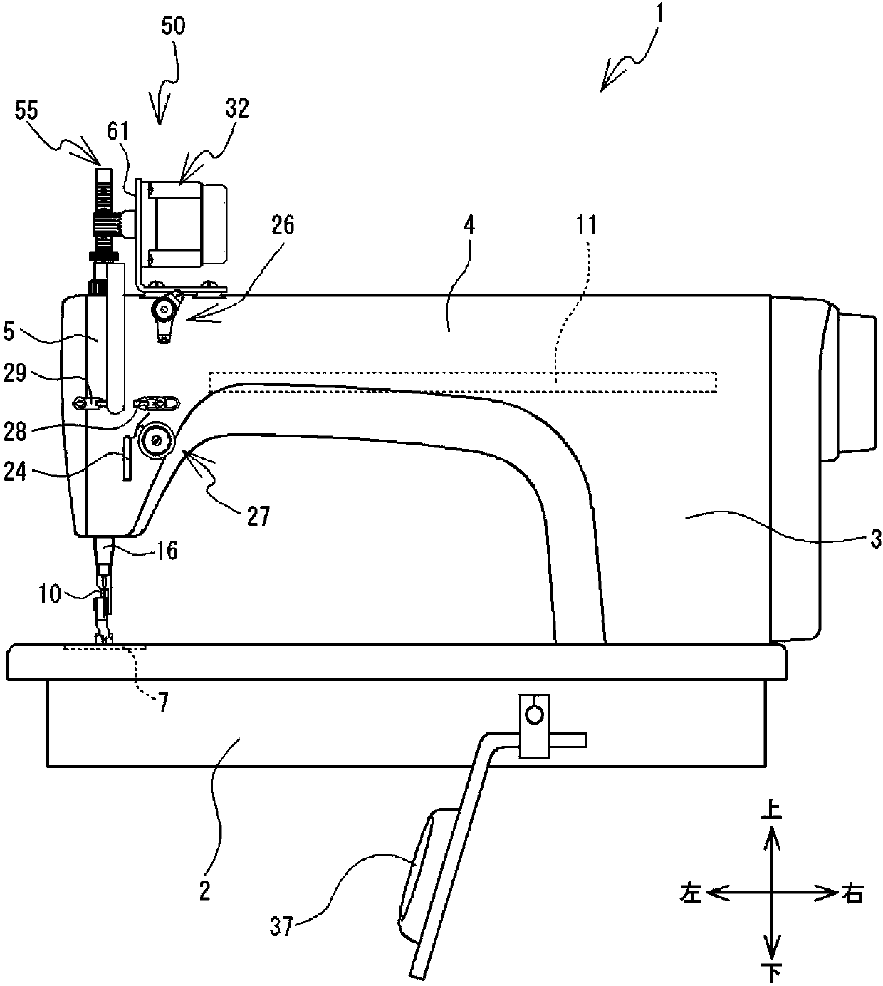
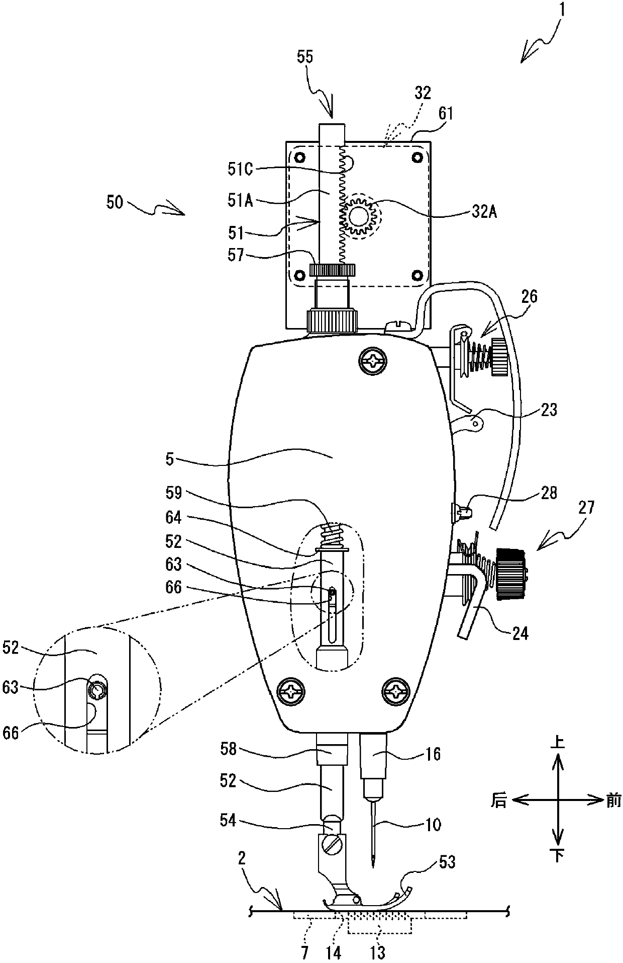
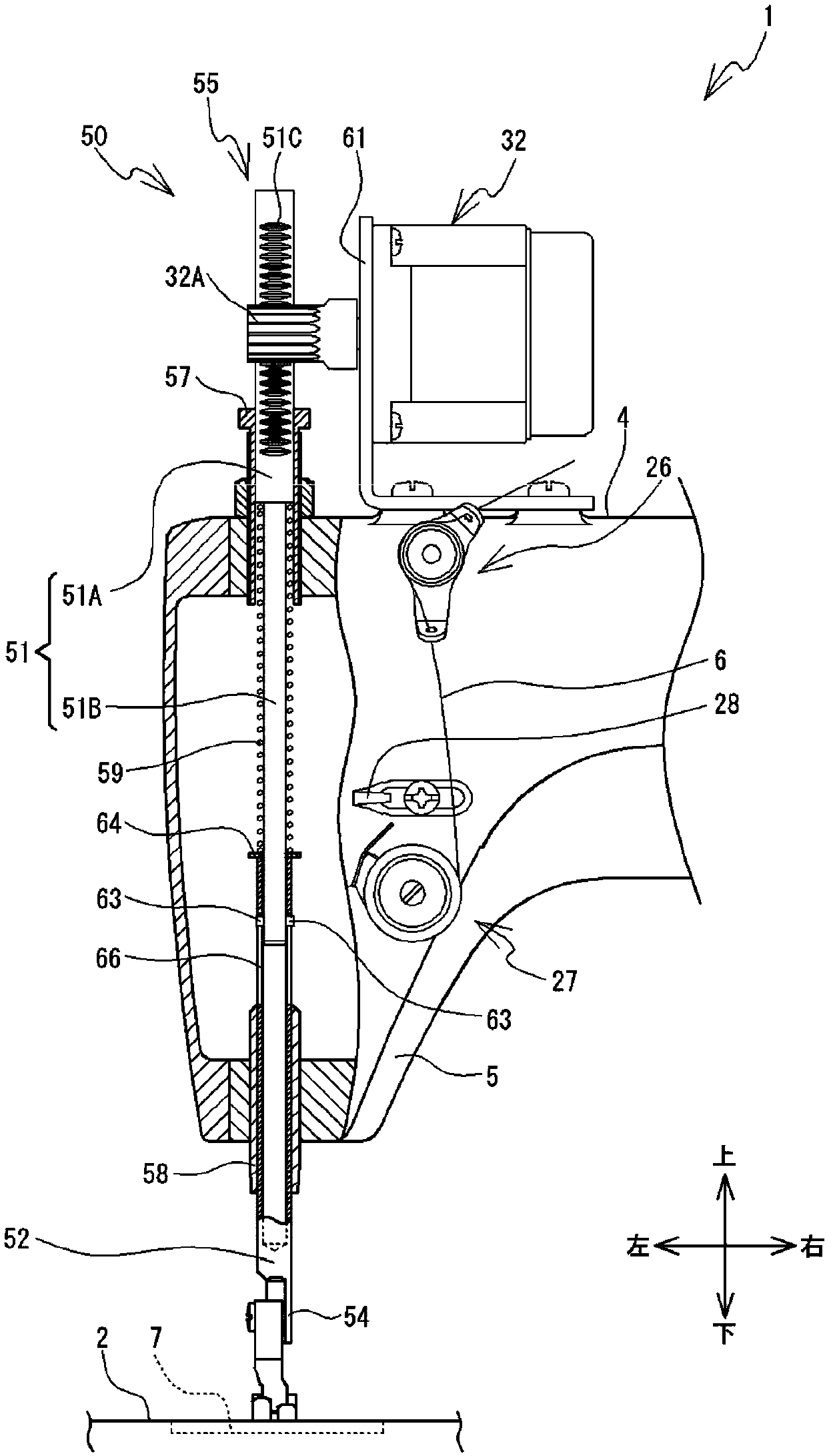
[0033] Hereinafter, embodiments of the present invention will be described with reference to the drawings. In the following description, left and right, front and rear, and up and down shown by arrows in the drawings are used.

[0034] refer to figure 1 , figure 2 The structure of the sewing machine 1 will be described. The sewing machine 1 has a base portion 2 , a pillar portion 3 and an arm portion 4 . The machine base part 2 is attached to the workbench, and the machine base part 2 extends in the left-right direction. The needle plate 7 is attached to the upper surface of the machine base 2 . The operator will cloth 9 (refer to Figure 11 ) is placed on the machine base 2 and the needle plate 7. The needle plate 7 has a needle hole 8 (refer to Figure 11 ) and feed tooth hole 14. The pin hole 8 is circular in plan view. The cloth feed tooth hole 14 has a long diameter in the front-rear direction, and the cloth feed tooth hole 14 is located on the left, rear, right...


PUM


Abstract

The invention relates to a sewing machine and a control method thereof. The sewing machine will not damage the cloth. The sewing machine comprises a needle bed, a presser foot, and a presser foot motor. The needle bed supports cloth. The presser foot can move up and down above the needle bed. The presser foot motor can drive the presser foot to move between a press position and a separate position. The presser foot presses the cloth in the press position, and is separated from the cloth in the separate position. An operator grasps cloth between the needle bed and presser foot in the press position and applies force on the cloth. The presser foot moves upwards from the press position. When the presser foot moves upwards to a predetermined distance from the press position, CPU controls the presser foot motor to make the presser foot move to the separate position.

Description

technical field [0001] The invention relates to a sewing machine and a control method for the sewing machine. Background technique [0002] There is known a sewing machine that presses cloth. The sewing machine disclosed in Japanese Patent Laid-Open No. 102792 of 2005 has a holding frame, a rotation motor, an X-axis motor, and a Y-axis motor. The holding frame has a lower frame and an upper frame. The operator places the fabric to be sewn on the lower frame. The upper frame is connected to the lower frame so as to be rotatable relative to the lower frame. The upper frame rotates between a pressing position where the upper frame is when the cloth is pressed between the upper frame and the lower frame, and a release position where the upper frame is when the cloth placed on the lower frame is released. location. The holding frame holds the cloth by pressing the cloth at the pressing position by the upper frame. Rotating the motor enables the upper frame to rotate between...

Claims


Application Information

Patent Timeline
Patent Type & Authority Applications(China)
IPC IPC(8): D05B29/02D05B29/06
CPCD05B29/02D05B29/06
Inventor 竹村徹
Owner BROTHER KOGYO KK
Why Eureka
Try Eureka