Displacement loading three-dimensional test device and method for shield tunnelling surface stability analysis

A technology of test device and driving surface, applied in the direction of using stable tension/pressure test material strength, measurement device, analysis material, etc., can solve the problem of not truly reflecting the three-dimensional soil stress-strain relationship, stress environment difference, and reliable analysis results Sexual doubts, etc.

Pending Publication Date: 2018-02-06
BEIJING FORESTRY UNIVERSITY
View PDF5 Cites 2 Cited by
  • Summary
  • Abstract
  • Description
  • Claims
  • Application Information

AI Technical Summary

Problems solved by technology

[0002] In the prior art, when analyzing the stability of the tunnel shield tunneling face, the soil is usually cut longitudinally or transversely, and the test is carried out by plane loading to study the soil pressure distribution of the soil in front of the tunneling face and the loss of the tunneling surface. The slippage of the soil in front of the tunnel when it is stable, among which there are many studies on the longitudinal section. However, simply studying the longitudinal section or cross section of the tunnel cannot reflect the entire situation

Method used


Image

  • Displacement loading three-dimensional test device and method for shield tunnelling surface stability analysis
  • Displacement loading three-dimensional test device and method for shield tunnelling surface stability analysis
  • Displacement loading three-dimensional test device and method for shield tunnelling surface stability analysis

Examples


Embodiment Construction

[0043] The specific implementation manners of the present invention will be further described in detail below in conjunction with the accompanying drawings and embodiments. The following examples are used to illustrate the present invention, but are not intended to limit the scope of the present invention.

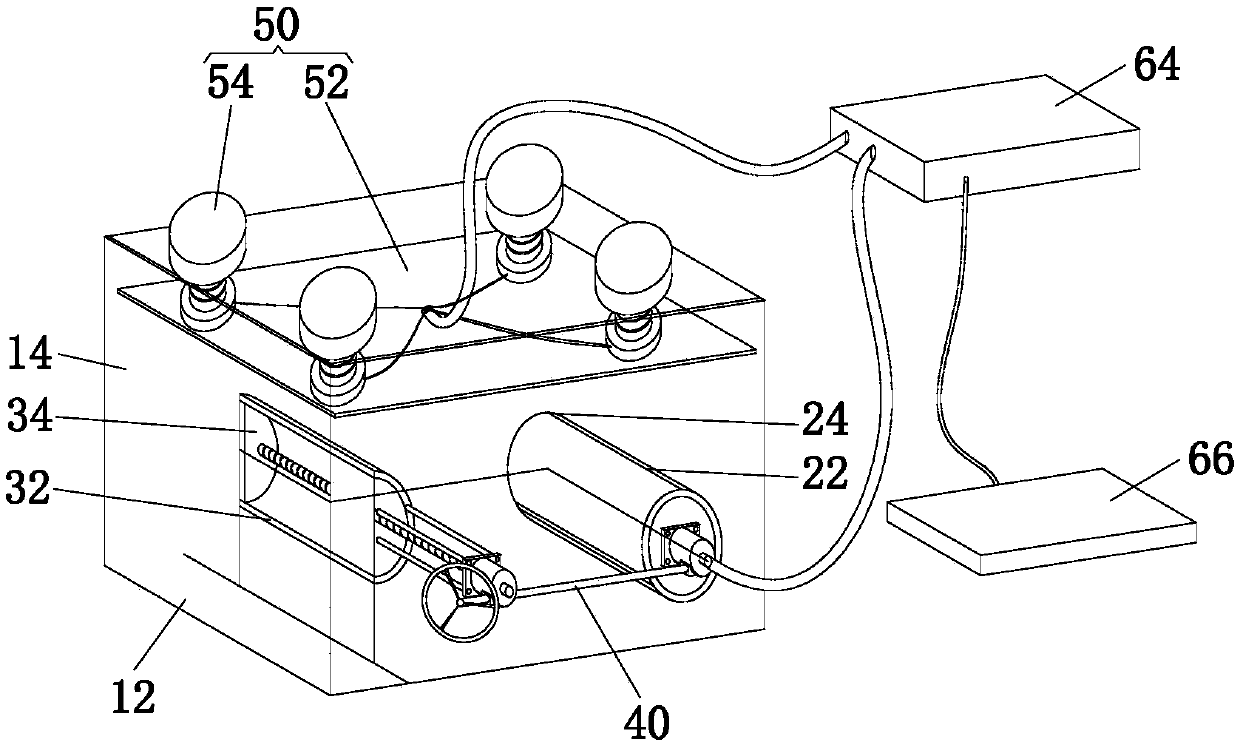
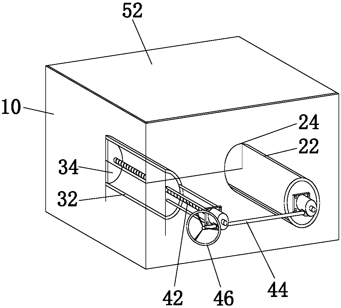
[0044] see figure 1 with figure 2 As shown, the present invention proposes a three-dimensional displacement loading test device for the stability analysis of the shield tunneling surface, which is used to simulate tunnel excavation, and the three-dimensional displacement loading test device for the stability analysis of the shield tunneling surface includes a housing 10, a confining pressure simulation mechanism 50. Displacement synchronous loading mechanism 40, at least two filling and measuring components.

[0045] The housing 10 includes a bottom wall 12, a side wall 14 and a top wall, the bottom wall 12 is closed at the lower end opening of the side wall 14, and the...


PUM


Abstract

The invention discloses a displacement loading three-dimensional test device and a displacement loading three-dimensional test method for shield tunnelling surface stability analysis. The device comprises a shell, a confining pressure simulating mechanism, a displacement synchronous loading mechanism, at least two parts of packing and a measuring assembly; the shell comprises a bottom wall, at least one partially transparent side wall and a top wall; the confining pressure simulating mechanism comprises a pressurizing plate and at least two lifting machines; the bottom wall, the side wall andthe pressurizing plate enclose to form a packing box body; synchronous lifting of the lifting machines drives the pressurizing plate to move up and down; the displacement synchronous loading mechanismcomprises a driving machine, a cylindrical cylinder wall, a circular baffle plate which seals and covers the inner end of the cylindrical cylinder wall, a semi-cylindrical cylinder wall and a semicircular baffle plate which seals and covers the inner end of the semi-cylindrical cylinder wall; the driving machine drives the two baffle plates to move synchronously; the packing is arranged in the packing box body in a layered manner; the colours of adjacent layers of the packaging are different; the measuring assembly comprises soil pressure sensors on the circular baffle plate, a confining pressure sensor on the pressurizing plate, an acquisition instrument and a processor. According to the displacement loading three-dimensional test device and the displacement loading three-dimensional test method for the shield tunnelling surface stability analysis, model testing study is performed on the pressure distribution and the slip state of a soil body of the shield tunnelling surface.

Description

technical field [0001] The invention relates to the technical field of tunnel shielding, in particular to a displacement loading three-dimensional test device and method for stability analysis of a shield tunneling surface. Background technique [0002] In the prior art, when analyzing the stability of the tunnel shield tunneling face, the soil is usually cut longitudinally or transversely, and the test is carried out by plane loading to study the soil pressure distribution of the soil in front of the tunneling face and the loss of the tunneling surface. For the slippage of the soil ahead when the tunnel is stable, there are many studies on the longitudinal section. However, simply studying the longitudinal section or cross section of the tunnel cannot reflect the entire situation of the soil ahead when the excavation face is unstable. Even if the longitudinal section and cross section of the tunnel excavation surface are studied at the same time on different test devices, a...

Claims


Application Information

Patent Timeline
IPC IPC(8): G01N3/08
CPCG01N3/08G01N2203/0003G01N2203/0019G01N2203/0676G01N2203/0682
Inventor 刘学彦袁大军
Owner BEIJING FORESTRY UNIVERSITY
Why Eureka
Try Eureka