Supercharge Your Innovation With Domain-Expert AI Agents!

A coupler automatic centering device and rail vehicle rescue method

An automatic centering and coupler technology, which is applied in the field of rail vehicles, can solve the problem that the coupler cannot be automatically connected, and achieve the effect of increasing the range of the coupler and increasing the range of the coupler

Active Publication Date: 2019-06-07
ZHUZHOU ELECTRIC LOCOMOTIVE CO LTD
View PDF10 Cites 0 Cited by
  • Summary
  • Abstract
  • Description
  • Claims
  • Application Information

AI Technical Summary

Problems solved by technology

[0007] Aiming at the problem that the couplers of trams and subway projects with small-radius plane curves (such as suspension monorail and straddle monorail projects with R50m small-radius plane curves on the main line) cannot realize automatic coupling, the present invention aims to provide a coupler automatic centering device and rail vehicle rescue method, the centering device can solve the problem that the coupler has an automatic centering function in the waiting state, and when the small radius plane curve is connected, it can automatically rotate the coupler horizontally and horizontally to a fixed angle, and can make the coupler It is in the rotation locked state, solving the technical problem of automatic coupling of the coupler on the small radius curve

Method used


Image

  • A coupler automatic centering device and rail vehicle rescue method
  • A coupler automatic centering device and rail vehicle rescue method
  • A coupler automatic centering device and rail vehicle rescue method

Examples


Embodiment 1

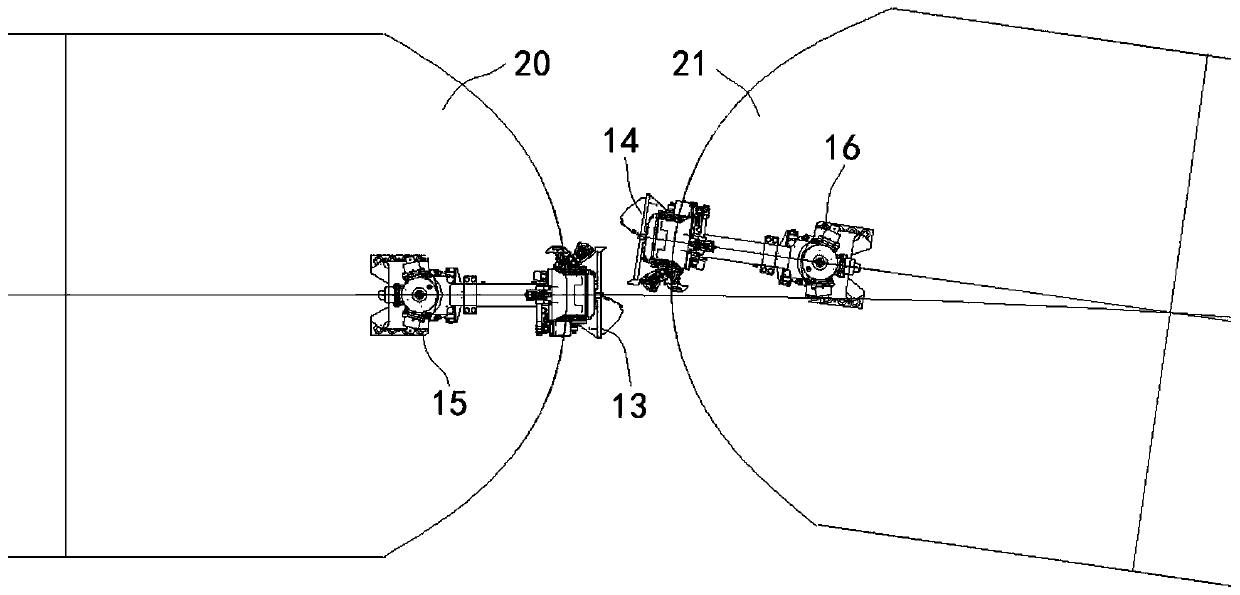
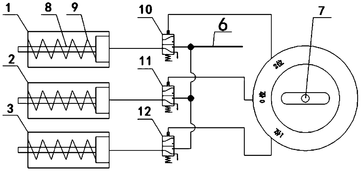
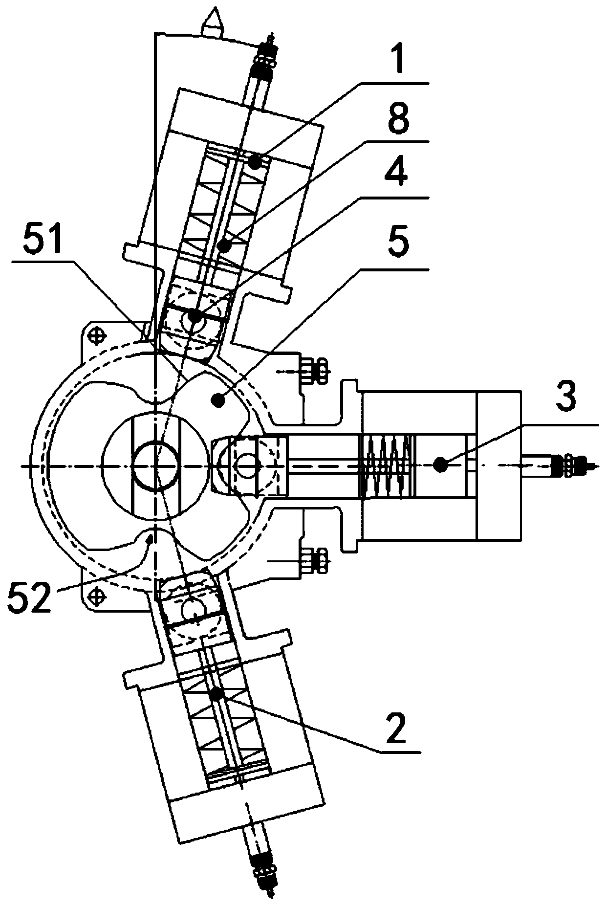
[0043] An automatic centering device for a coupler. By operating a control knob and selecting the activation cylinder of the centering device, the coupler can automatically rotate a certain angle in the horizontal direction, increase the coupling range of the coupler, and realize the automatic coupling of the coupler on a small curve.

[0044] enter image 3 and 4As shown, the coupler automatic centering device includes a coupler buffer housing, a cam disc 5 , a first cylinder 1 , a second cylinder 2 , a third cylinder 3 , a cylinder piston rod 8 and a cylinder roller 5 . The cam disc 5 is connected to the coupler buffer housing through parts such as key grooves and fasteners, so that the cam disc 5 drives the coupler to rotate when the cam disc 5 rotates. The air duct of the vehicle inflates the corresponding cylinder to control the cylinder piston rod 8 to move forward. When the cylinder was in the non-ventilated state, the return spring in the cylinder moved the cylinder ...

Embodiment 2

[0051] A coupler centering device such as Figure 7-10 shown, which includes

[0052] Internal gear cam disc 32, which is used to be fixedly connected with the coupler buffer housing;

[0053] An external gear transmission mechanism 31, which is engaged with the internal gear cam disc 32 for transmission; and

[0054] A driving device, which is used to drive the external gear transmission mechanism 31 and / or the internal gear cam disc 32 to rotate an angle;

[0055] The internal gear cam disc 32 and / or the external gear transmission mechanism 31 are provided with a notch, and the outer side of the internal gear cam disc 32 is provided with a telescopic rod for keeping the center line of the coupler and the center line of the vehicle body in alignment;

[0056] When the telescopic rod stretches out, it cooperates with the notch, and the internal gear cam plate 32 and / or the external gear transmission mechanism 31 are locked together with the telescopic rod; The notch disenga...


PUM


Abstract

The invention discloses an automatic aligning device for train couplers and a rail train rescue method. The automatic aligning device for the train couplers comprises a cam disc fixedly connected witha train coupler buffer shell; a first notch, a second notch and a third notch are formed in the peripheral surface of the cam disc; an air cylinder is arranged on the outer side of each notch correspondingly, and the three air cylinders communicate with a train air pipe through corresponding air supply pipelines; and each air supply pipeline is provided with a valve, and each valve is controlledby a three-position control switch to be opened and closed to enable only one of the three air cylinders to be kept in a ventilation state. The technical problem of automatic coupling of the vehicle couplers on the small-radius curve is solved.

Description

technical field [0001] The invention relates to an automatic coupler centering device and a rail vehicle rescue method, belonging to the technical field of rail vehicles. Background technique [0002] Generally, the coupler of tram and subway projects is equipped with a centering device that cannot rotate automatically, such as the Chinese utility model patent CN201120010340.4, the horizontal rotation of the coupler is less than ±15°, and the cam and the coupler rotate together to push the roller out of the groove of the cam. The piston rod of the air cylinder reversely compresses the disc spring, thereby providing a greater counter-rotational moment to return the coupler to the alignment of the centerline and the longitudinal centerline of the car body. [0003] The main function of the centering device is to prevent the coupler from swinging horizontally and causing interference between the coupler, the hood and the shroud when the train is in the waiting state. [0004] ...

Claims


Application Information

Patent Timeline
Patent Type & Authority Patents(China)
IPC IPC(8): B61G7/06B61G7/12
CPCB61G7/06B61G7/12
Inventor 匡希超帅纲要黄豪金希红苏永章刘永强曾文娟刘旭李涛苏柯
Owner ZHUZHOU ELECTRIC LOCOMOTIVE CO LTD
Features
  • R&D
  • Intellectual Property
  • Life Sciences
  • Materials
  • Tech Scout
  • Unparalleled Data Quality
  • Higher Quality Content
  • 60% Fewer Hallucinations
Learn More