
Unit sleeve tooth telescopic device

A technology of telescopic devices and sets of teeth, which is applied to bridge parts, bridges, buildings, etc., can solve problems such as component fatigue, complex structure, wear and tear, etc., to achieve the change of large occupied space, improved safety and durability, and displacement The effect of empowerment

Pending Publication Date: 2018-02-09
ANHUI TRANSPORTATION HLDG GRP CO LTD
View PDF0 Cites 0 Cited by
  • Summary
  • Abstract
  • Description
  • Claims
  • Application Information

AI Technical Summary

Problems solved by technology

Under this traditional thinking, the functions of the telescopic device are mutually restricted, the structure is very complicated, and the components are fatigued and worn seriously.
The performance is that the telescopic device has frequent diseases, frequent maintenance, and complicated replacement

Method used


Image

  • Unit sleeve tooth telescopic device
  • Unit sleeve tooth telescopic device
  • Unit sleeve tooth telescopic device

Examples


Embodiment 1

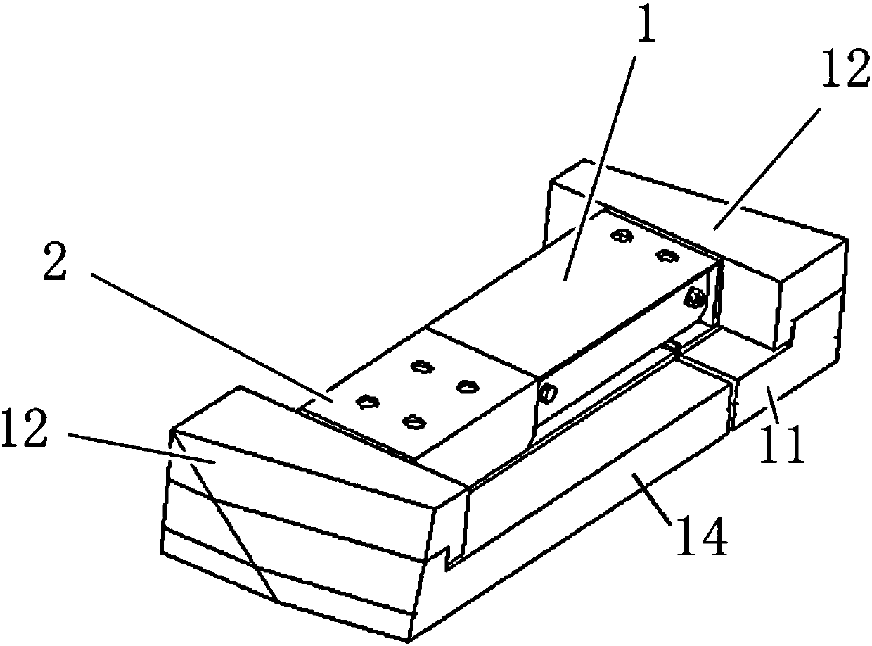
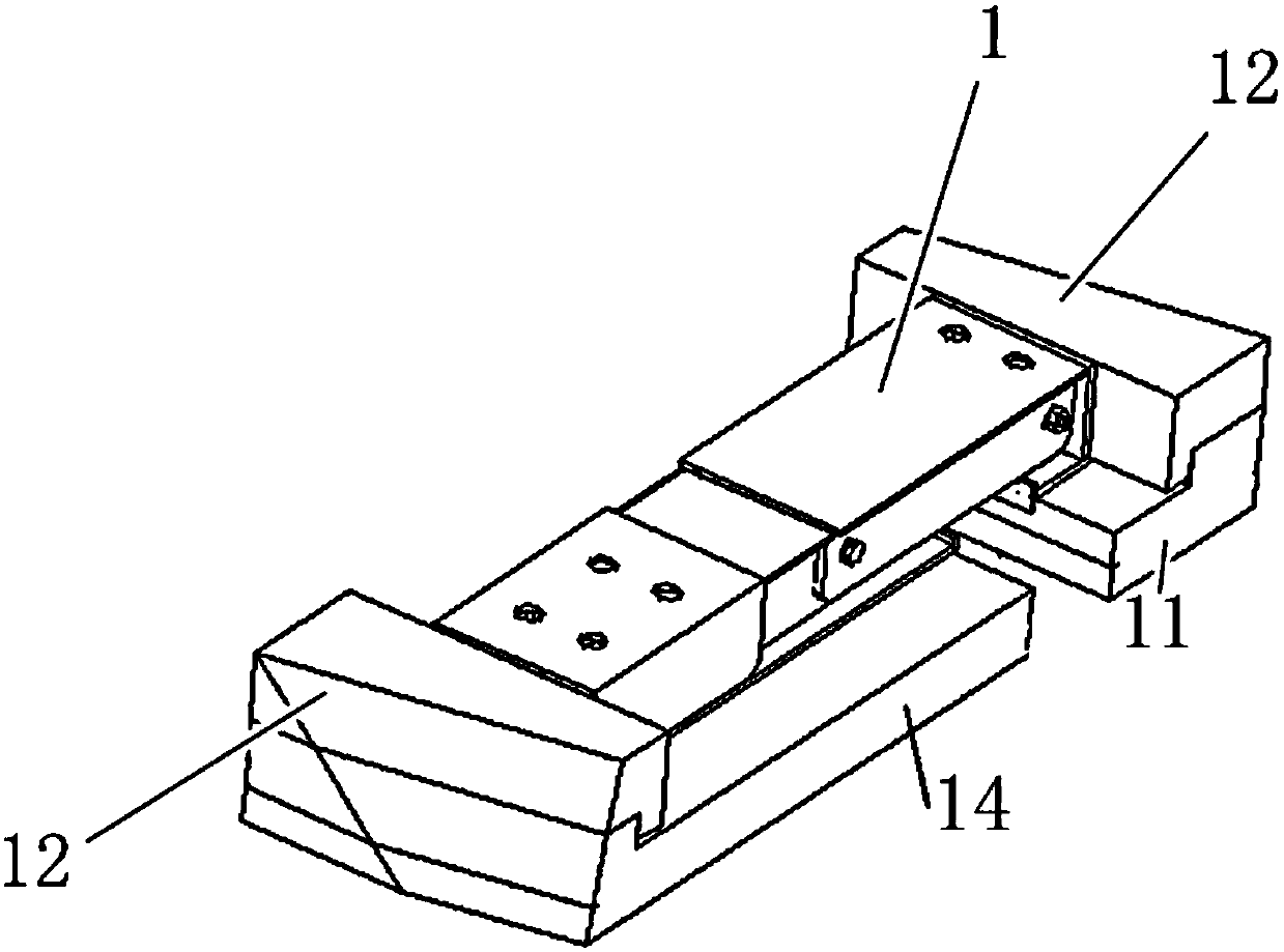
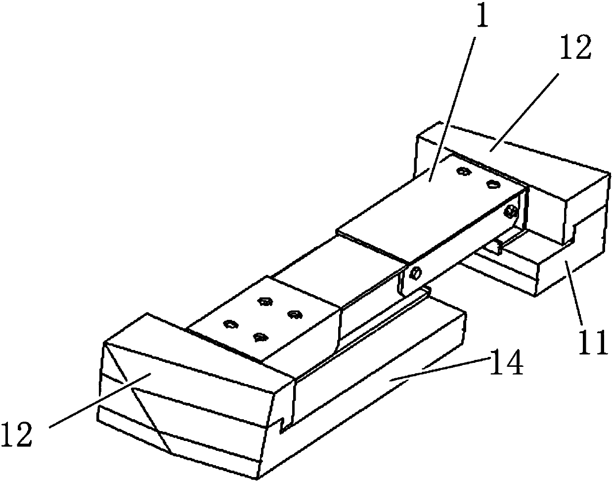
[0028] A kind of unit sleeve gear telescopic device, such as Figure 1-4 As shown, it is arranged between the first beam end 11 and the second beam end 14. The unit set tooth telescopic device includes a unit sliding member 1 and a unit set tooth member 2. The unit sliding member 1 is set in the unit set tooth member 2. The unit gear member 2 guides and limits, forming a shallow telescopic device with stable functions;

[0029] The unit sliding member 1 includes a slot-spanning slot 3 and a sliding slot 7, the sliding slot 7 is arranged on the second beam end 14, a fixed base 5 is provided on the first beam end 11, and one end of the slot-spanning slot 3 is connected by a rear bolt hinge 4 On the fixed base 5 on the first beam end 11, the fixed base 5 is fixed on the first beam end 11 by anchor bolts 10, and the other end of the cross slot 3 is connected to the second beam end 14 by the front bolt hinge 6 On the sliding groove 7, a double-hinge spanning structure that can ada...

Embodiment 2

[0036] Such as Figure 1-3 As shown, a unit set tooth telescopic device with a stretching amount of 240 mm includes a unit sliding member 1 and a unit set tooth member 2 . The unit sliding member 1 is fitted in the unit gear member 2 after crossing the seam, and is guided and limited by the unit gear member 2 to form a shallow telescopic device with stable functions.

[0037] Such as Figure 4 , The unit sliding member 1 and the unit set gear member 2 adopt groove-shaped welded members with high strength and rigidity and low overall height. Component materials are Q345C steel plates with a thickness of 6mm and 8mm.

[0038] Such as Figure 4 The unit sliding member 1 connects one end of the cross slot 3 to the fixed base 5 on the first beam end 11 with the M24 rear bolt hinge 4, and the other end is connected to the second beam end 14 with the M24 front bolt hinge 6 On the sliding groove 7 on the top, a kind of double-hinge spanning structure that can adapt to the lateral,...


PUM


Abstract

The invention relates to a unit sleeve tooth telescopic device which is arranged between a first beam end and a second beam end. The unit sleeve tooth telescopic device is characterized in that the unit sleeve tooth telescopic device comprises a unit sliding member and a unit sleeve tooth member, wherein the unit sliding member is sleeved with the unit sleeve tooth member and is guided and limitedby the unit sleeve tooth member, and thus the shallow stratification telescopic device with stable functions is formed. Compared with the prior art, the unit sleeve tooth telescopic device has the unique working principle, the working mode of the telescopic device is clear, the shifting ability is enhanced, the members are mutually engaged, function playing is reliable, and safety and durabilityare improved. The disadvantage that an existing telescopic device is large in occupied space size is overcome, and the conditions for mounting, detecting, maintenance and replacement are better through the shallow stratification, modularization and assemblage characteristics.

Description

technical field [0001] The invention belongs to the technical field of civil engineering, and in particular relates to a unit sleeve tooth expansion device. Background technique [0002] Expansion devices are one of the key structures of bridges. The main types are rubber expansion joints, steel expansion joints, modular steel expansion joints, comb-shaped expansion joints, and seamless expansion joints. [0003] Due to the various types of bridge structures and the complex deformation state of the main girder, there are many types of expansion devices with their own characteristics in the history of their development. So far, how to choose a telescopic device with suitable functions has often become a difficult problem. [0004] Currently commonly used telescopic devices are often dedicated to realizing multiple functions such as seam spanning, telescoping, vertical rotation, plane rotation, and plane swing simultaneously on an overall structure. Under this traditional th...

Claims


Application Information

Patent Timeline
IPC IPC(8): E01D19/06
CPCE01D19/065
Inventor 胡可王宏斌曹光伦胡为民王凯席进
Owner ANHUI TRANSPORTATION HLDG GRP CO LTD
Learn More