Screw-type British air nozzle inflation joint

The technology of a screw-type British-style and inflatable joint is applied in the field of British-style gas nozzle inflatable joints, which can solve the problems of high manufacturing cost, inconvenient operation, complicated structure, etc., and achieve the effects of reducing cost, improving applicability and convenient operation.

Inactive Publication Date: 2019-06-28
BETO ENG & MARKETING
View PDF6 Cites 0 Cited by
  • Summary
  • Abstract
  • Description
  • Claims
  • Application Information

AI Technical Summary

Problems solved by technology

[0003] When you want to inflate the British air nozzle, you must use an inflation joint dedicated to inflating the British air nozzle. As far as the current common British air nozzle inflation joint is concerned, not only the structure is too complicated, but the manufacturing cost is also reduced. Higher problem, more inconvenient operation disadvantage

Method used


Image

  • Screw-type British air nozzle inflation joint
  • Screw-type British air nozzle inflation joint
  • Screw-type British air nozzle inflation joint

Examples


Embodiment Construction

[0036] In order to have a further understanding and recognition of the features and characteristics of the present invention, the following preferred embodiments are listed below and described in conjunction with the drawings:

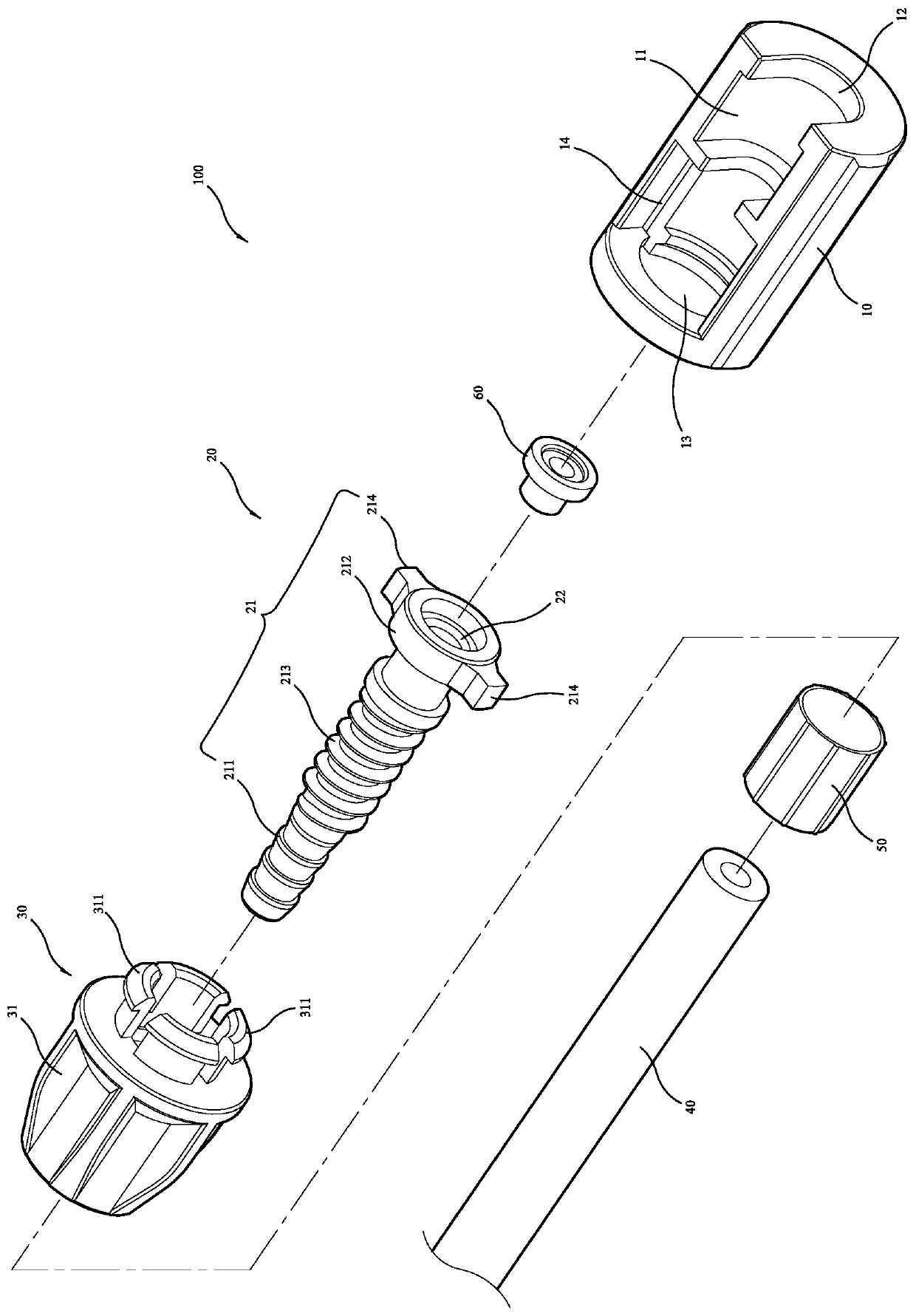
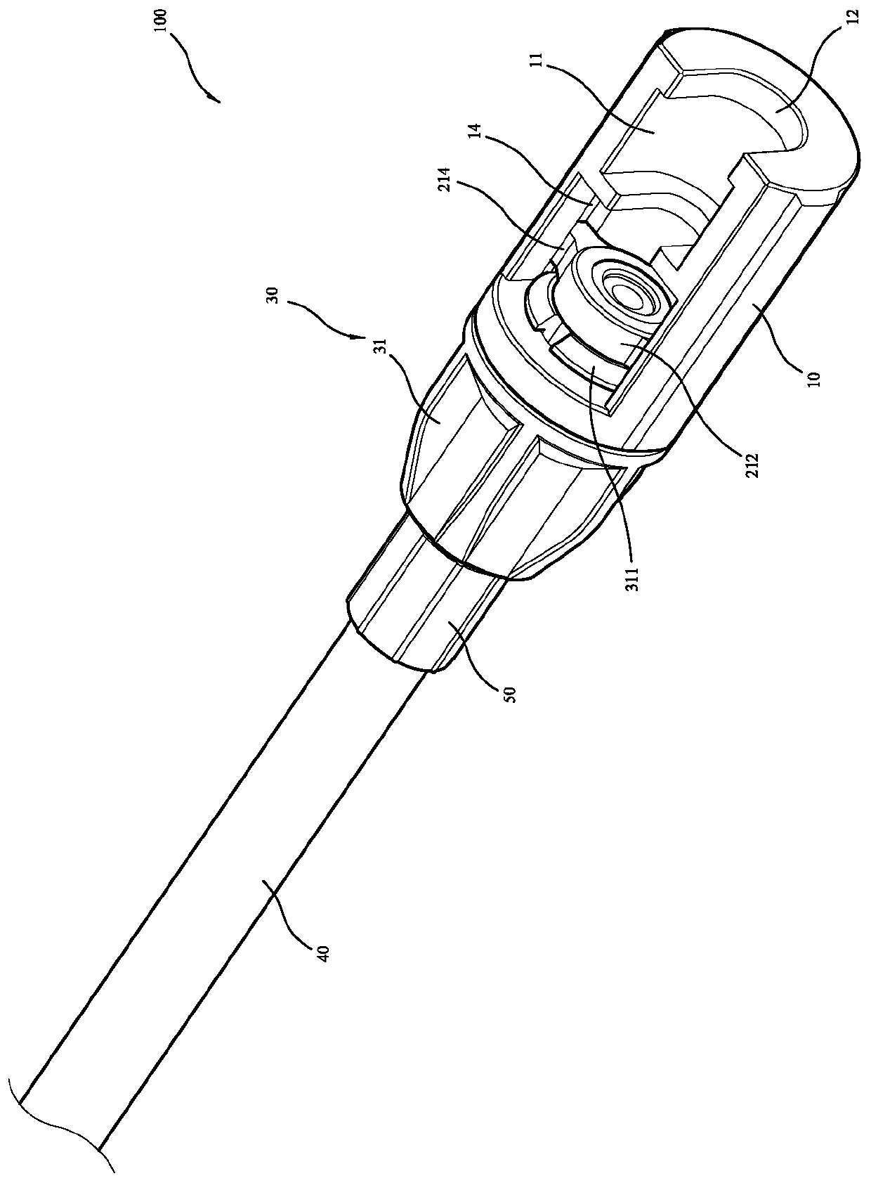
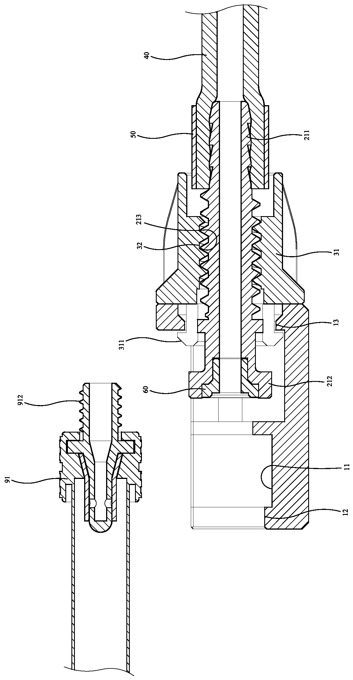
[0037] see Figure 1 to Figure 7 , which is a rotary type British air nozzle inflation joint 100 provided in a preferred embodiment of the present invention, which mainly includes an air nozzle socket 10, a joint 20, a knob 30, a trachea 40, and a bundle of sleeves 50 and a soft compression ring 60, wherein:

[0038] see Figure 1 to Figure 3 One side of the air nozzle socket 10 extends from the outside to the inside and is recessed with a limiting cavity 11, and one end of the air nozzle socket 10 extends axially inwards to have an air nozzle opening 12 communicating with the limiting cavity 11 The other end of the air nozzle socket 10 extends axially inwardly with a joint opening 13 communicating with the limiting cavity 11 , and the limiting cavit...


PUM


Abstract

The invention discloses a rotating forced type English style air nozzle inflating connector. The rotating forced type English style air nozzle inflating connector mainly comprises an air nozzle connection base, a connector body, a rotary knob and an air pipe; one side of the air nozzle connection base extends and sinks from outside to inside to form a limiting containing groove; one end of the airnozzle connection base extends inwards in the axial direction to form an air nozzle opening; the other end of the air nozzle connection base extends inwards in the axial direction to form a connectoropening; the two opposite sides of the limiting containing groove are provided with two slide grooves extending in the axial direction; the connector body is provided with a connector main body and an inflating hole; the connector main body is provided with an external thread and two sliders; the sliders are connected in the slide grooves of the air nozzle connection base in a sliding manner, andcan reciprocate along the slide grooves; the rotary knob is provided with a rotary knob body and an internal thread penetrating the rotary knob body; the rotary knob body and the air nozzle connection base can be combined on the spot in a shaft rotating manner; the internal thread of the rotary knob and the external thread of the connector body are in threaded connection; and the air pipe is connected with the connector body. In this way, the functions that the structure is simple, operation is convenient, and applicability is good are achieved.

Description

technical field [0001] The invention relates to the field of British air nozzle inflation joints, in particular to a rotary type English air nozzle inflation joint. Background technique [0002] At present, there are many types of valves for bicycle tires, which are mainly divided into American, French and British valves. Because each has its own advantages and disadvantages, each type has its own preference. [0003] When you want to inflate the British air nozzle, you must use an inflation joint dedicated to inflating the British air nozzle. As far as the current common British air nozzle inflation joint is concerned, not only the structure is too complicated, but the manufacturing cost is also reduced. The higher the problem, the more inconvenient it is to operate. Contents of the invention [0004] The purpose of the present invention is to provide a rotary-type English-style air nozzle inflation joint with simple structure, convenient operation and good applicability...

Claims


Application Information

Patent Timeline
Patent Type & Authority Patents(China)
IPC IPC(8): F16L19/02
CPCF16L19/0206
Inventor 王罗平
Owner BETO ENG & MARKETING
Why Eureka
Try Eureka