

Corneal shaping lens
A technology of orthokeratology lenses and corneas, applied in glasses/goggles, optics, instruments, etc.
- Summary
- Abstract
- Description
- Claims
- Application Information
AI Technical Summary
Problems solved by technology
Method used
Image

Examples
Embodiment Construction
[0052] The following specific examples are only used to further explain the present invention, but the present invention is not limited to the following specific embodiments. Any changes based on these embodiments will fall within the protection scope of the present invention as long as they conform to the spirit and scope of the principles of the present invention.
[0053] The refractive state of the cornea is mainly determined by its radius of curvature. In actual clinical application, the commonly used conversion relationship between the radius of curvature of the cornea and the diopter of the cornea is:
[0054] (1)
[0055] Among them, K is the diopter of the cornea in D, R is the radius of curvature of the front surface of the cornea in mm, and n is the refractive index of the cornea. For example, n can be 1.3375.
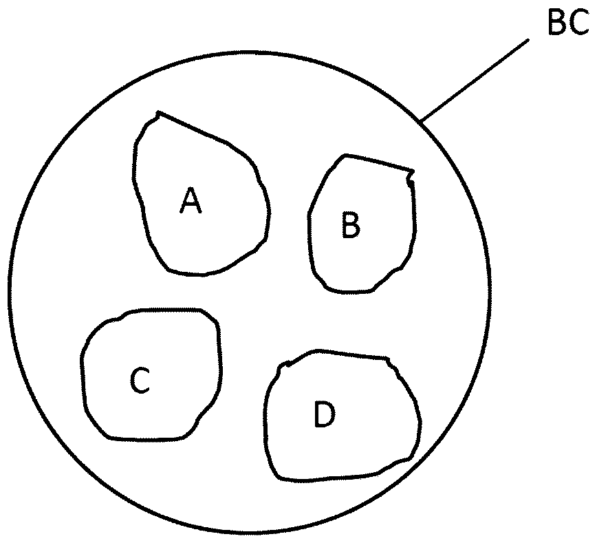
[0056] Such as figure 1 As shown, the orthokeratology lens includes an inner surface IS facing the cornea of a person's eye when worn, and an outer...
PUM
| Property | Measurement | Unit |
|---|---|---|
| Diameter | aaaaa | aaaaa |
| Diameter | aaaaa | aaaaa |
Abstract
Description
Claims
Application Information