An automatic control switch light device

A technology for switching lights and equipment, applied in lighting and heating equipment, components of lighting devices, lighting devices, etc., can solve problems such as trouble for users to turn on lights

Active Publication Date: 2019-12-24
JIANGXI SUNWAY CHEM CO LTD
View PDF6 Cites 0 Cited by
  • Summary
  • Abstract
  • Description
  • Claims
  • Application Information

AI Technical Summary

Problems solved by technology

[0006] In order to overcome the disadvantages of the existing switch light method, which is troublesome for the user to turn on the light when it is dark, the technical problem to be solved by the present invention is to provide an automatic control system that can automatically switch the light, and the switch can still be used normally after the equipment fails. switching light equipment

Method used


Image

  • An automatic control switch light device
  • An automatic control switch light device
  • An automatic control switch light device

Examples


Embodiment 1

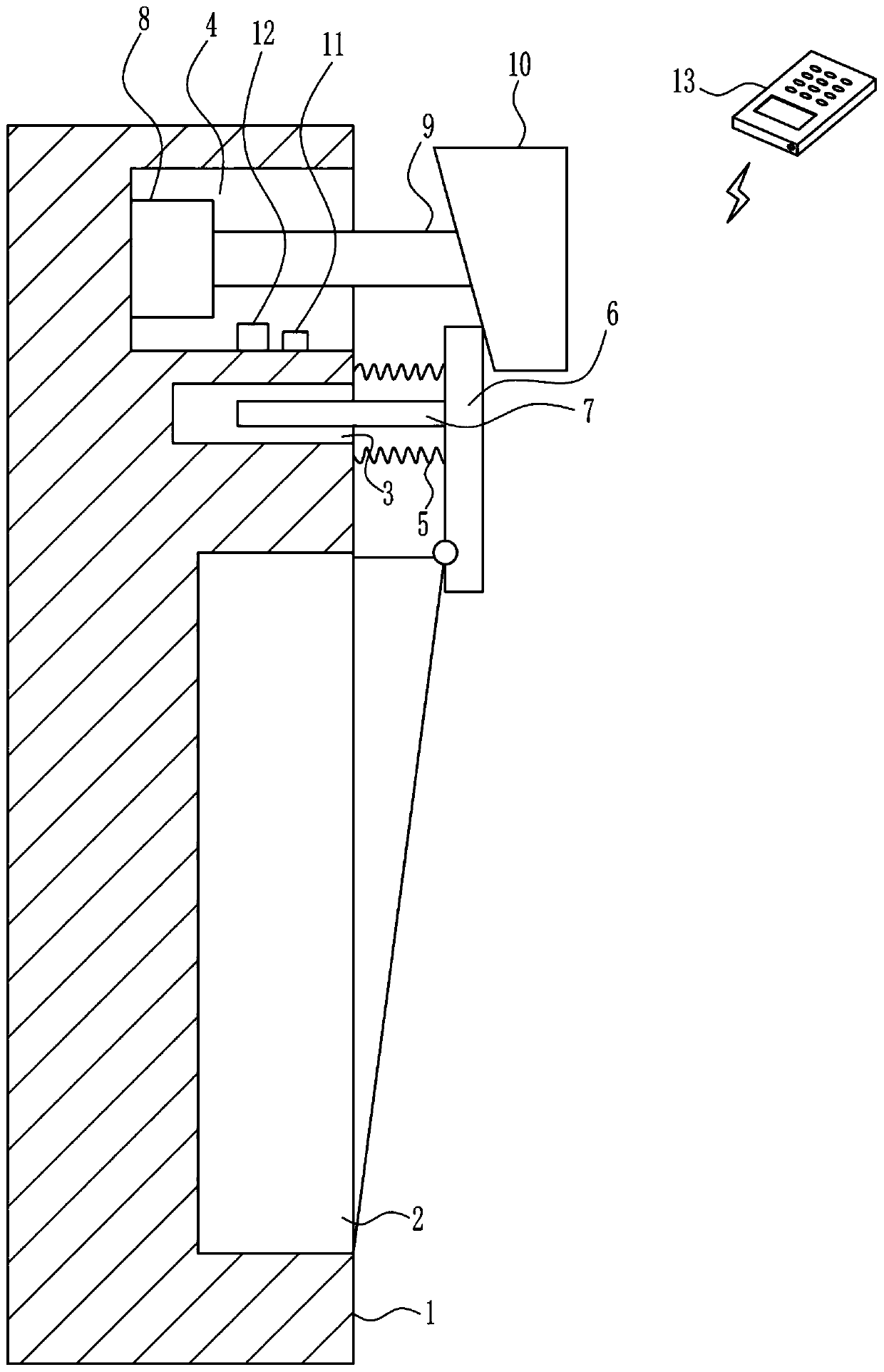
[0023] An automatically controlled switching light device such as Figure 1-3 As shown, it includes a spring 5, a push plate 6, a fixed rod 7, a motor 8, a rotating shaft 9, a cam 10, a controller 11, a wireless receiver 12 and a terminal 13. The right side of the wall 1 is provided with a switch body 2, and the switch body 2 The upper right side of the upper wall 1 is provided with a first groove 3 and a second groove 4, the first groove 3 is located below the second groove 4, two springs 5 ​​are connected to the upper right side of the wall 1, and the springs 5 is located on the upper and lower sides of the first groove 3, the right end of the spring 5 is connected with a push plate 6, the lower left side of the push plate 6 is rotationally connected with the upper right side of the switch body 2, and the upper left side of the push plate 6 is provided with a fixed rod 7, fixed The left end of the rod 7 is located in the first groove 3, the left middle part in the second gro...

Embodiment 2

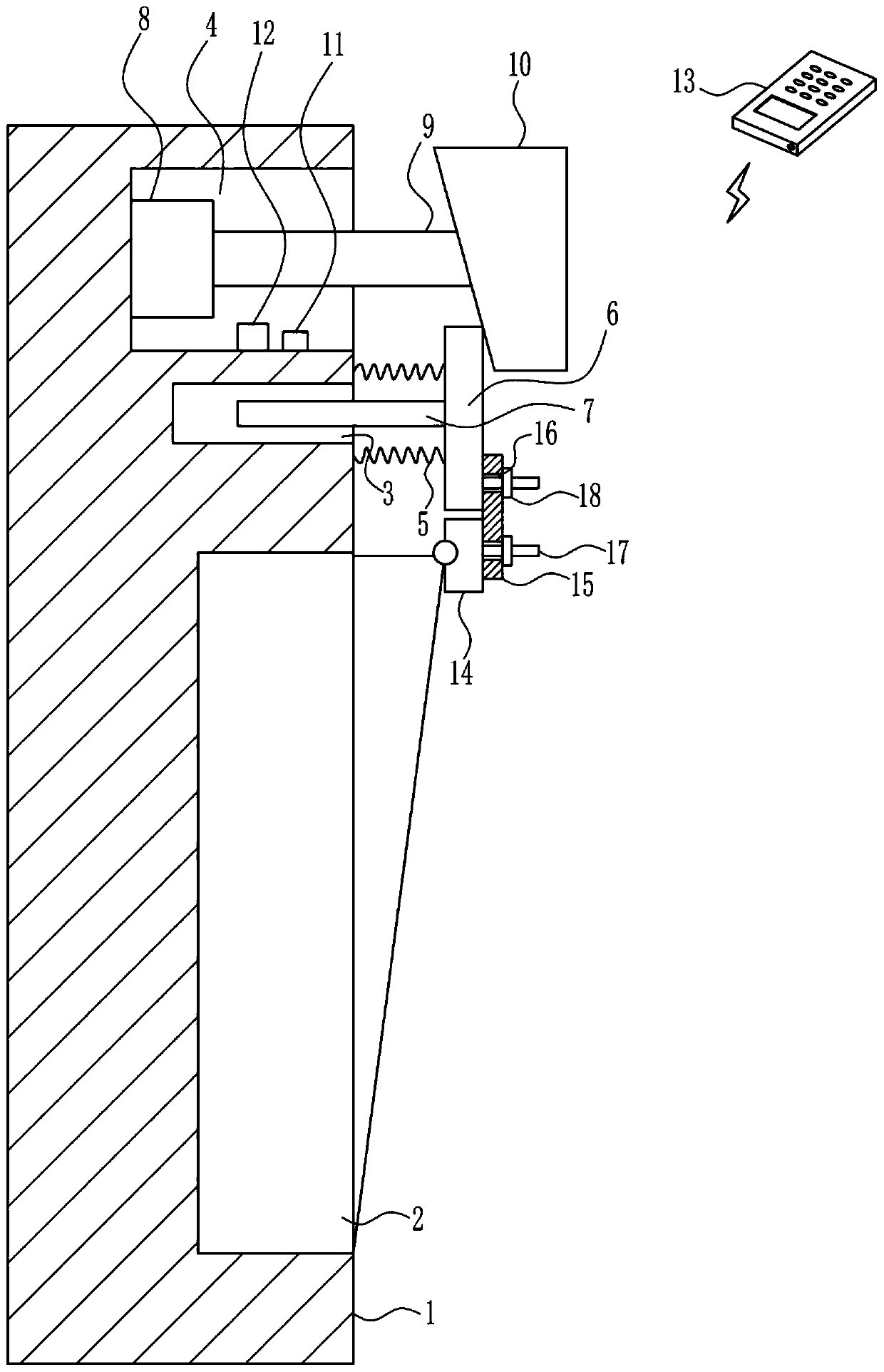
[0025] An automatically controlled switching light device such as Figure 1-3 As shown, it includes a spring 5, a push plate 6, a fixed rod 7, a motor 8, a rotating shaft 9, a cam 10, a controller 11, a wireless receiver 12 and a terminal 13. The right side of the wall 1 is provided with a switch body 2, and the switch body 2 The upper right side of the upper wall 1 is provided with a first groove 3 and a second groove 4, the first groove 3 is located below the second groove 4, two springs 5 ​​are connected to the upper right side of the wall 1, and the springs 5 is located on the upper and lower sides of the first groove 3, the right end of the spring 5 is connected with a push plate 6, the lower left side of the push plate 6 is rotationally connected with the upper right side of the switch body 2, and the upper left side of the push plate 6 is provided with a fixed rod 7, fixed The left end of the rod 7 is located in the first groove 3, the left middle part in the second gro...

Embodiment 3

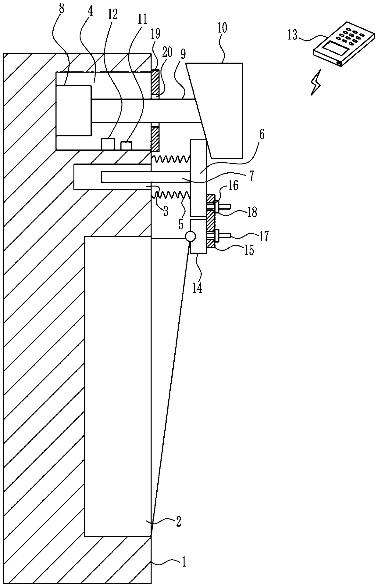
[0028] An automatically controlled switching light device such as Figure 1-3 As shown, it includes a spring 5, a push plate 6, a fixed rod 7, a motor 8, a rotating shaft 9, a cam 10, a controller 11, a wireless receiver 12 and a terminal 13. The right side of the wall 1 is provided with a switch body 2, and the switch body 2 The upper right side of the upper wall 1 is provided with a first groove 3 and a second groove 4, the first groove 3 is located below the second groove 4, two springs 5 ​​are connected to the upper right side of the wall 1, and the springs 5 is located on the upper and lower sides of the first groove 3, the right end of the spring 5 is connected with a push plate 6, the lower left side of the push plate 6 is rotationally connected with the upper right side of the switch body 2, and the upper left side of the push plate 6 is provided with a fixed rod 7, fixed The left end of the rod 7 is located in the first groove 3, the left middle part in the second gro...


PUM


Abstract

The invention relates to lamp turning-on and turning-off equipment, in particular to automatic-controlled lamp turning-on and turning-off equipment. The technical problem to be solved by the inventionis to provide the automatic-controlled lamp turning-on and turning-off equipment, which can automatically turn on and turn off a lamp; and a switch still can be normally used after the equipment is broken down. In order to solve the technical problems, the invention provides the automatic-controlled lamp turning-on and turning-off equipment. The automatic-controlled lamp turning-on and turning-off equipment comprises springs, a push plate, a fixed rod, a motor, a rotating shaft, a cam, a controller and the like; a switch body is arranged on the right side of a wall; a first groove and a second groove are formed above the right side of the wall at the upper part of the switch body; the first groove is positioned below the second groove; two springs are connected above the right side of thewall; and the springs are positioned on the upper and lower sides of the first groove. The automatic-controlled lamp turning-on and turning-off equipment achieves automatic control effects of automatically turning on and turning off the lamp and still normally using the switch after the equipment is broken down; and the switch can be controlled through a terminal, so that a bulb can be automatically brightened and extinguished.

Description

technical field [0001] The invention relates to a switch lamp device, in particular to an automatically controlled switch lamp device. Background technique [0002] A switch is an electronic component that can open a circuit, interrupt the current flow, or allow it to flow to other circuits. The most common switches are human-operated electromechanical devices that have one or more electrical contacts. The closing of the contact indicates that the electronic contact is conducting and allows the current to flow, and the open circuit of the switch indicates that the electronic contact is not conducting and forms an open circuit and does not allow the current to flow. The switch can control the bulb to turn on and off. [0003] The existing way of switching lights has the disadvantage that the user needs to grope for the position of the switch to turn on the light when it is dark. When the user needs to turn on the light, he must go to the position of the switch to turn on th...

Claims


Application Information

Patent Timeline
Patent Type & Authority Patents(China)
IPC IPC(8): F21V23/00F21V23/04
CPCF21V23/003F21V23/0435
Inventor 钟国强张倩洪楷
Owner JIANGXI SUNWAY CHEM CO LTD
Why Eureka
Try Eureka