Bill issuing part and method and bill printing device and method

A technology for printing equipment and bills, which is applied in the fields of bill issuing components and bill printing equipment, and can solve the problem of inability to issue two or more kinds of bills.

Pending Publication Date: 2018-03-02
SHENZHEN YIHUA COMP +2
View PDF7 Cites 3 Cited by
  • Summary
  • Abstract
  • Description
  • Claims
  • Application Information

AI Technical Summary

Problems solved by technology

[0005] In view of this, the embodiment of the present invention provides a bill issuing component and method as well as a bill printing device and method to solve the problem in the prior art that one bill issuing device cannot issue two or more bills at the same time. technical flaw

Method used


Image

  • Bill issuing part and method and bill printing device and method
  • Bill issuing part and method and bill printing device and method
  • Bill issuing part and method and bill printing device and method

Examples


Embodiment 1

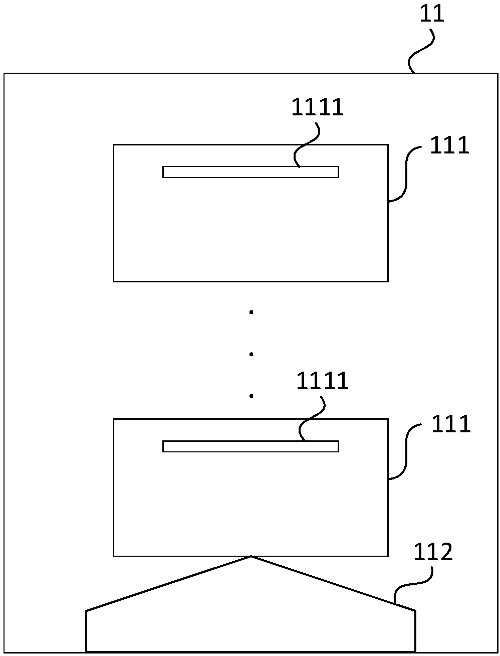
[0036] figure 1 A structural diagram of a bill issuing unit 11 provided in Embodiment 1 of the present invention. In this embodiment, the bill issuing unit 11 specifically includes: a ticket box lifting platform 112 and at least two ticket boxes 111. At least two ticket boxes 111 are controlled by the bottom The top stack is placed on the ticket box lifting platform 112. What needs to be explained here is that, figure 1 The shape and installation position of the ticket box lifting platform 112 and the specific position where the ticket outlet 1111 is located in the ticket box 111 are exemplary representations. The actual shape and installation position of the ticket box lifting platform 112 and the actual location of the ticket outlet 1111 The specific location of box 111 can be compared with figure 1 shown differently.

[0037] Among them, the ticket box 111 includes a ticket outlet 1111, which is used to store the same or different specifications of bills to be exported, ...

Embodiment 2

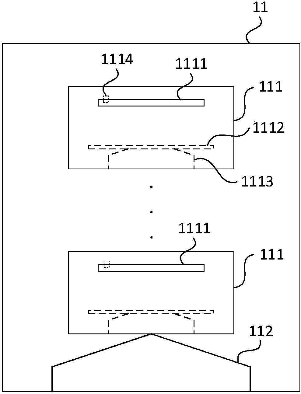
[0049] figure 2 It is a structural diagram of a bill issuing unit 11 provided in Embodiment 2 of the present invention. The present embodiment is optimized on the basis of the above-mentioned embodiments. In this embodiment, the ticket box 111 is optimized to include: a bill support plate 1112, a ticket pressing platform 1113 and a ticket sorting device 1114; the bill support plate 1112 is placed on the press On the lifting platform 1113, it is used to lift the bills to be output stored in the ticket box 111; the ticket pressing lifting platform 1113 is arranged at the bottom of the ticket box 111, and is used to raise or lower the ticket supporting plate 1112 according to the second lifting command sent by the control device The ticket distributing device 1114 is arranged at one end of the ticket outlet 1111, and is used to send out the bills to be output stored in the ticket box 111 from the ticket outlet 1111 according to the ticket issuing instruction. What needs to be e...

Embodiment 3

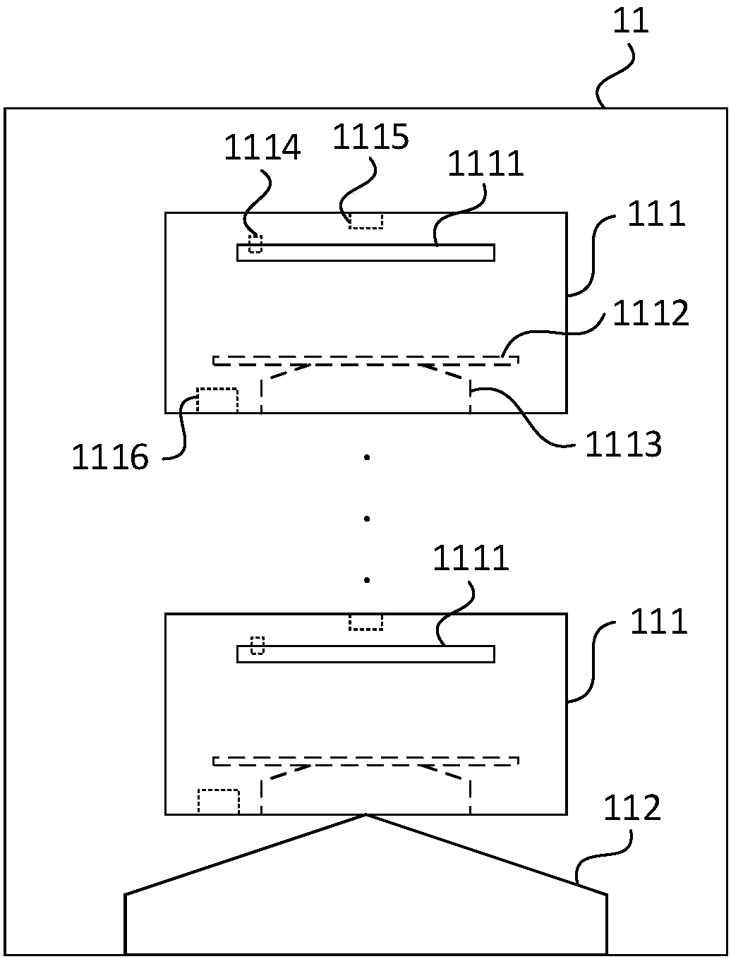
[0056] image 3 It is a structural diagram of a bill issuing component 11 provided in Embodiment 3 of the present invention. This embodiment is optimized on the basis of the above-mentioned embodiments. In this embodiment, the ticket box 111 is optimized to include: a bill holder 1112 plate, a ticket press lifting platform 1113, a ticket sorting device 1114, a pressure sensor 1115 and a lifting control device 1116 ;The bill supporting plate 1112 is placed on the ticket press lifting platform 1113, and is used to lift the bills to be output stored in the ballot box 111; The contact pressure of the bill, and send the contact pressure test data to the lifting control device 1116; the lifting control device 1116 is used to send the second lifting instruction to the ticket press lift platform 1113 according to the contact pressure test data; the ticket press lift platform 1113 is arranged on the ticket The bottom of the box 111 is used to raise or lower the bill pallet 1112 accord...


PUM


Abstract

The embodiment of the invention discloses a bill issuing part and method and a bill printing device and method. The bill issuing part comprises a bill box lifting table and at least two bill boxes. The bill boxes are stacked and placed on the bill box lifting table from bottom to top. Each bill box comprises a bill outlet for storing same or different-specification to-be-output bills and sending the stored to-be-output bills out of the bill outlet according to a bill output instruction sent by a control device, and a bill box lifting platform for controlling the bill boxes to commonly vertically move up or down according to a received first lifting instruction sent by the control device so as to adjust the bill outlet to be aligned with the bill boxes at the input end of a bill output channel. According to the technical scheme, the issuing operation of various different types of bills can be conducted by means of one bill issuing device, the bill pick-up time is saved for clients, andthe use experience of the clients is improved.

Description

technical field [0001] The embodiments of the present invention relate to the technical field of bill issuing, and in particular, to a bill issuing component and method, and bill printing equipment and method. Background technique [0002] As the business volume of financial, postal and other institutions has increased year by year, the demand for bills has also increased significantly. Due to the cumbersome filling of the contents of the bills, most financial, postal and other institutions now use automatic bill printing and distribution equipment to complete the bills. payment. [0003] The existing automatic printing and issuing equipment for bills can automatically process the printing and issuing of bills, greatly reducing the workload of the staff, but the existing automatic printing and issuing equipment for bills can only handle the printing and issuing of one kind of bills, and cannot simultaneously Tickets are printed and issued. [0004] Due to the wide variety ...

Claims


Application Information

Patent Timeline
Patent Type & Authority Applications(China)
IPC IPC(8): G07F17/26
CPCG07F17/266
Inventor 陈胜斌
Owner SHENZHEN YIHUA COMP
Why Eureka
Try Eureka