Over-current turn-off test circuit, method and device of converter valve

A test circuit, overcurrent technology, applied in the direction of measuring devices, measuring electricity, measuring electrical variables, etc., can solve problems such as the inability to reach the steady-state junction temperature of IGBT and the parameters of different reactors.

Active Publication Date: 2018-03-06
GLOBAL ENERGY INTERCONNECTION RES INST CO LTD
View PDF5 Cites 11 Cited by
  • Summary
  • Abstract
  • Description
  • Claims
  • Application Information

AI Technical Summary

Problems solved by technology

[0004] In view of this, the embodiment of the present invention provides a converter valve over-current shut-off test circuit, method and device to solve the problem of over-current shut-off test of the converter valve in the prior art by means of water temperature heating. The problem that different reactor parameters need to be configured when the steady-state junction temperature of the IGBT cannot be reached or when an overcurrent is formed through an increased short-circuit current branch

Method used


Image

  • Over-current turn-off test circuit, method and device of converter valve
  • Over-current turn-off test circuit, method and device of converter valve
  • Over-current turn-off test circuit, method and device of converter valve

Examples


Embodiment Construction

[0019] In order to make the purpose, technical solutions and advantages of the embodiments of the present invention clearer, the technical solutions in the embodiments of the present invention will be clearly and completely described below in conjunction with the drawings in the embodiments of the present invention. Obviously, the described embodiments It is a part of embodiments of the present invention, but not all embodiments. Based on the embodiments of the present invention, all other embodiments obtained by those skilled in the art without creative efforts fall within the protection scope of the present invention.

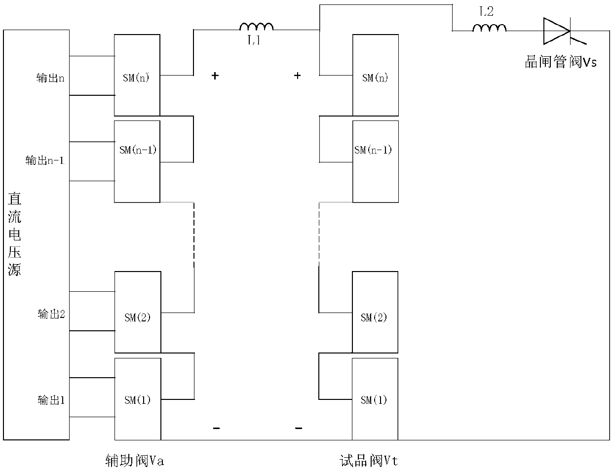
[0020] An embodiment of the present invention provides a converter valve overcurrent shutdown test circuit, such as figure 1 As shown, the converter valve overcurrent shutdown test circuit includes: power supply, auxiliary valve Va, sample valve Vt, load reactor L1, current limiting reactor L2 and thyristor valve Vs. The above-mentioned power supply can be, ...


PUM


Abstract

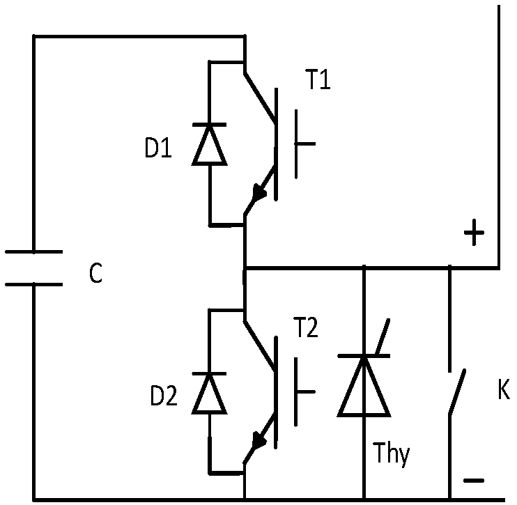
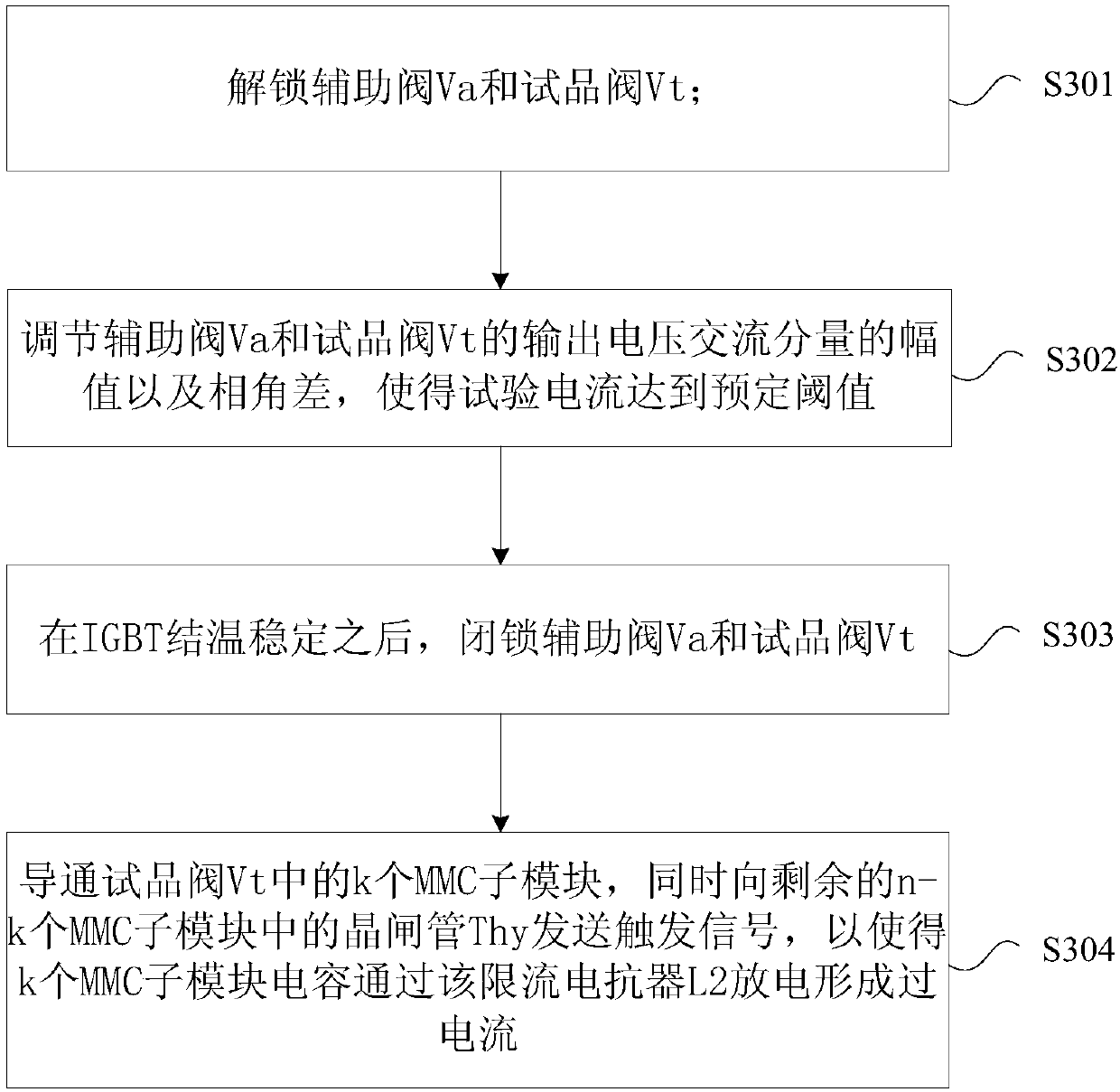
The invention provides an over-current turn-off test circuit, method and device of a converter valve. The circuit is composed of a power supply, an auxiliary valve, a sample valve, a load reactor, a current limiting reactor and a thyristor valve. The auxiliary valve is formed by series connection of m MMC sub modules. The sample valve is formed by series connection of n MMC sub modules. The load reactor is connected between the auxiliary valve and the sample valve. The current limiting reactor and the thyristor valve are connected in series and the series unit is connected in parallel with thesample valve; and an anode of the thyristor valve is connected with the current limiting reactor and a cathode of the thyristor valve is connected with a negative electrode of the sample valve. M pairs of independent output ports at the output terminal of the power supply are connected with the MMC sub module capacitors of the auxiliary valve to charge the auxiliary valve. Therefore, a problem that the steady-state junction temperature of the IGBT can not be reached by means of water temperature heating during the over-current turn-off testing process of the converter valve or different reactor parameters need to be configured when over currents are formed by an added short-circuit current branch in the prior art is solved.

Description

technical field [0001] The invention relates to the technical field of flexible DC power transmission in electric power systems, in particular to a test circuit, method and device for overcurrent shutdown of a converter valve. Background technique [0002] Flexible HVDC (Voltage Source Converter Based HVDC, VSC-HVDC) technology based on Modular Multilevel Converter (MMC) has been widely used in power systems and has significantly changed the power transmission The structure of the grid improves the performance of the grid. With the continuous improvement of the voltage level and transmission capacity of the MMC-HVDC system, higher requirements are placed on the reliability of its key equipment - the MMC valve, especially for various extreme currents, voltages and thermal stresses under fault conditions. The ability to stress puts forward higher requirements. Therefore, before the MMC valve is put into operation, a series of targeted inspections are required to test whether...

Claims


Application Information

Patent Timeline
Patent Type & Authority Applications(China)
IPC IPC(8): G01R31/00
CPCG01R31/003
Inventor 杨俊许彬王秀环高冲周军川王高勇
Owner GLOBAL ENERGY INTERCONNECTION RES INST CO LTD
Why Eureka
Try Eureka