Electrical connector

A technology for electrical connectors and docking surfaces, applied in the field of electrical connectors that can prevent terminal damage, can solve problems such as the impact of the electrical connection between the card module and the circuit board, the enhancement of the antenna effect, and the impact of signal transmission, etc., to reduce the antenna effect Effect

Active Publication Date: 2018-03-13
DEYI PRECISION ELECTRONIC IND CO LTD PANYU
View PDF6 Cites 2 Cited by
  • Summary
  • Abstract
  • Description
  • Claims
  • Application Information

AI Technical Summary

Problems solved by technology

Usually, in order to guide the insertion of the card module, the terminal will continue to extend a guide structure on the contact part. When the card module is inserted, it will first contact the guide structure and then guide it to the contact part to electrically connect with it. Such a guide structure If the design is poor, it is easy to cause the terminals to pin when the card module is inserted, and damage the terminals, thereby affecting the electrical connection between the card module and the circuit board.
At the same time, the extended guide structure is electrically connected to the contact part, thereby strengthening the antenna effect and having a greater impact on signal transmission

Method used


Image

  • Electrical connector
  • Electrical connector
  • Electrical connector

Examples


Embodiment Construction

[0035] In order to facilitate a better understanding of the purpose, structure, features, and effects of the present invention, the present invention will now be further described in conjunction with the accompanying drawings and specific embodiments.

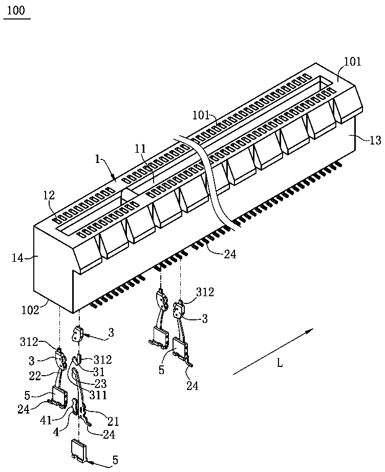
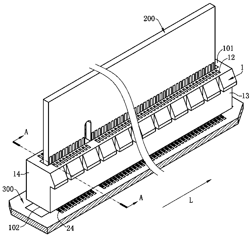
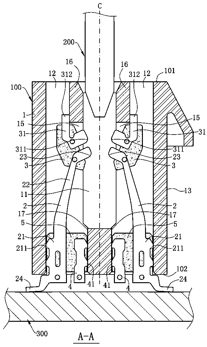
[0036] Please refer to Figure 1 to Figure 5 , is the main embodiment of an electrical connector 100 of the present invention, which includes an insulating body 1, a plurality of terminals 2 accommodated in the insulating body 1, an insulating member 3, a metal sheet 4 and a fixing member 5 . The electrical connector 100 is mounted on a circuit board 300. When a plug-in component 200 is plugged into the electrical connector 100, the plug-in component 200 passes through the electrical connector 100 and the circuit board. 300 electrical connection.

[0037] Please refer to Figure 1 to Figure 3 The insulating body 1 has an insertion space 11 extending along the longitudinal direction L, two side walls 13 located on both sides...


PUM


Abstract

The invention discloses an electrical connector. The electrical connector is used for a plug component to insert and comprises an insulation body and a plurality of terminals, wherein the insulation body is provided with an abutting surface and a plurality of terminal grooves, the abutting surface is provided with a plug space in a sunken way, the plurality of terminal grooves are arranged at oneside of the plug space, the plurality of terminals are respectively accommodated in the plurality of terminal grooves, each terminal is provided with a main body part, a connection part and a contactpart, the connection part sequentially extends towards the abutting surface from the main body part, the contact part is exposed out of the plug space, an insulator piece is arranged on the connectionpart and is provided with a guide part, the guide part is exposed out of the plug space and is near to the abutting surface relative to the contact part, and when the plug component enters the plug space, the plug component is in contact with the guide part to drive the terminal to deviate from the plug space and then is in electrical contact with the contact part, thus, an enough space can be enabled to be provided for the plug component to insert, the terminal can be effectively prevented from touching a pin, and the terminal is prevented from being damaged to cause influence on electricalconnection between the plug component and a circuit board.

Description

technical field [0001] The invention relates to an electrical connector, in particular to an electrical connector capable of preventing terminals from being damaged. Background technique [0002] A known card edge connector, which includes an insulating body and a number of butt terminals fixed to the insulating body, the insulating body is provided with a central slot for card module insertion and two side walls on opposite sides of the central slot Each side wall is provided with a plurality of receiving grooves penetrating through the side wall parallel to the insertion direction, and the plurality of docking terminals are respectively installed in the receiving grooves of the corresponding side wall. One side of the fixing part extends into the contact part in the central slot, and the welding foot extends from the other side of the fixing part beyond the insulating body. Usually, in order to guide the insertion of the card module, the terminal will continue to extend a...

Claims


Application Information

Patent Timeline
Patent Type & Authority Applications(China)
IPC IPC(8): H01R24/20H01R12/72H01R13/629
CPCH01R12/724H01R13/629H01R24/20
Inventor 蔡友华
Owner DEYI PRECISION ELECTRONIC IND CO LTD PANYU
Why Eureka
Try Eureka