A control system and control method based on auxiliary braking of new energy vehicles

A new energy vehicle, auxiliary braking technology, applied in the direction of electric braking system, vehicle components, electric vehicles, etc., can solve the problems of low control degree, prone to failure, reduced safety, etc., to broaden application conditions, improve Braking efficiency, the effect of prolonging the service life

Active Publication Date: 2019-11-26
CAMALUOYANGELECTROMECHANIC
View PDF5 Cites 0 Cited by
  • Summary
  • Abstract
  • Description
  • Claims
  • Application Information

AI Technical Summary

Problems solved by technology

For example, the utility model with the patent number CN203157745U discloses a vehicle braking system based on a supercapacitor, which mainly provides two loads that consume excess charge, one is a heater, the other is a resistor, and through two The simple switch is turned on or off to realize the consumption of excess power, but the control degree is not high, and the quality of the load cannot be detected in time, and it is prone to failure, and the failure cannot be diagnosed and processed in real time, and the service life of the battery is short
The invention with the patent number CN103532365B discloses a braking unit, which mainly introduces how to suppress the peak voltage generated by the high-power switching tube IGBT at the moment of turning off, so as to ensure the normal operation of the circuit, which mainly involves converters or frequency converters In the technical field of braking, the frequent conversion of converters or frequency converters can not guarantee the life of the battery, and the wear and tear of the main brake of the vehicle will reduce the safety.

Method used


Image

  • A control system and control method based on auxiliary braking of new energy vehicles
  • A control system and control method based on auxiliary braking of new energy vehicles
  • A control system and control method based on auxiliary braking of new energy vehicles

Examples


Embodiment Construction

[0039] Specific embodiments are given below in conjunction with the accompanying drawings, and the technical solution of the present invention is further clearly, completely and detailedly described. This embodiment is the best embodiment on the premise of the technical solution of the present invention, but the protection scope of the present invention is not limited to the following embodiments.

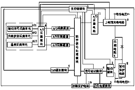
[0040] Such as figure 1 Shown is a schematic block diagram of the system of the present invention, a control system based on auxiliary braking of new energy vehicles, including a main control module 1, a digital signal processing module 2, a positive and negative power supply module 3, an A / D acquisition module 4, and CAN communication Module 5, signal drive module 6, drive module 7, drive protection circuit 8, power-on pre-charging circuit 9 and fault protection circuit 10, digital signal processing module 2, positive and negative power supply module 3, A / D acquisition module 4, C...


PUM


Abstract

Provided is a control system and method based on assisted braking of a new energy resource vehicle. The control system comprise a main control module, a digital signal processing module, a positive-negative power supply module, an A / D acquisition module, a CAN communication module, a signal driving module, a driving module, a drive protection circuit, an electrifying and pre-charging circuit and fault protection circuit, wherein the modules cooperate with each other, the circuit work normally, the logic is close, the response speed is high, and the control precision is high. The control methodadopts a main control program, an auxiliary control program, a normal working mode and a fault processing mode, wherein primary fault diagnosis and temperature fault diagnosis are included in the fault processing mode, the shortcoming of insufficient braking under specific conditions is overcome on the premise that braking of the original vehicle is not affected, normal and efficient work of thecircuits is ensured, the braking efficiency is improved, an application condition range is widened, a battery can be effectively protected, the service life of the battery is prolonged, abrasion of amain brake of the vehicle is reduced, and safe, reliable and quick braking of the vehicle is achieved.

Description

technical field [0001] The present invention relates to the technical field of vehicle braking control, more specifically, to a control system and control method based on new energy vehicle auxiliary braking. Background technique [0002] As we all know, with the increasingly prominent world energy crisis and environmental protection issues, countries all over the world pay more and more attention to new energy vehicles. In recent years, new energy vehicles have been vigorously promoted and used in my country. At present, hybrid and pure electric vehicles are the main vehicles, which are characterized by electric motors as part or all of their power sources. During the acceleration process, the motor can provide the required power source, while during the braking process, it works in the generator mode to charge the power battery or capacitor and generate reverse torque to realize electric regenerative braking. The battery may be fully charged due to long-term braking, or t...

Claims


Application Information

Patent Timeline
Patent Type & Authority Patents(China)
IPC IPC(8): B60L7/26B60L7/18B60L3/00
CPCB60L3/00B60L7/18B60L7/26Y02T90/16
Inventor 李奇峰黄国宁张学申郭玉峰马洲马向阳
Owner CAMALUOYANGELECTROMECHANIC
Why Eureka
Try Eureka