Novel push-pull type time switch

A timing switch, push-pull technology, applied in the field of switches, can solve the problems of unusable timing switches, large switching distance, inconvenient maintenance, etc., and achieve the effect of avoiding the replacement of push-pull rods, convenient replacement and convenient adjustment

Inactive Publication Date: 2018-03-23
CHENGDU KECHUANGCHENG TECH
View PDF4 Cites 1 Cited by
  • Summary
  • Abstract
  • Description
  • Claims
  • Application Information

AI Technical Summary

Problems solved by technology

[0004] Based on the above technical problems, the present invention provides a new type of push-pull timing switch, thereby solving the problem that the existing timing switch is adsorbed on the wall next to the switch to be controlled, and the switch to be controlled is controlled by a pressing device, but there is a timing switch. After the switch is adsorbed on the wall, the distance between it and the switch that needs to be controlled is too large, so that the timing switch cannot be used, and because the pressing device is in contact with the switch that needs to be controlled, it is easy to be damaged, and there is a technical problem of inconvenient maintenance

Method used


Image

  • Novel push-pull type time switch
  • Novel push-pull type time switch
  • Novel push-pull type time switch

Examples


Embodiment 1

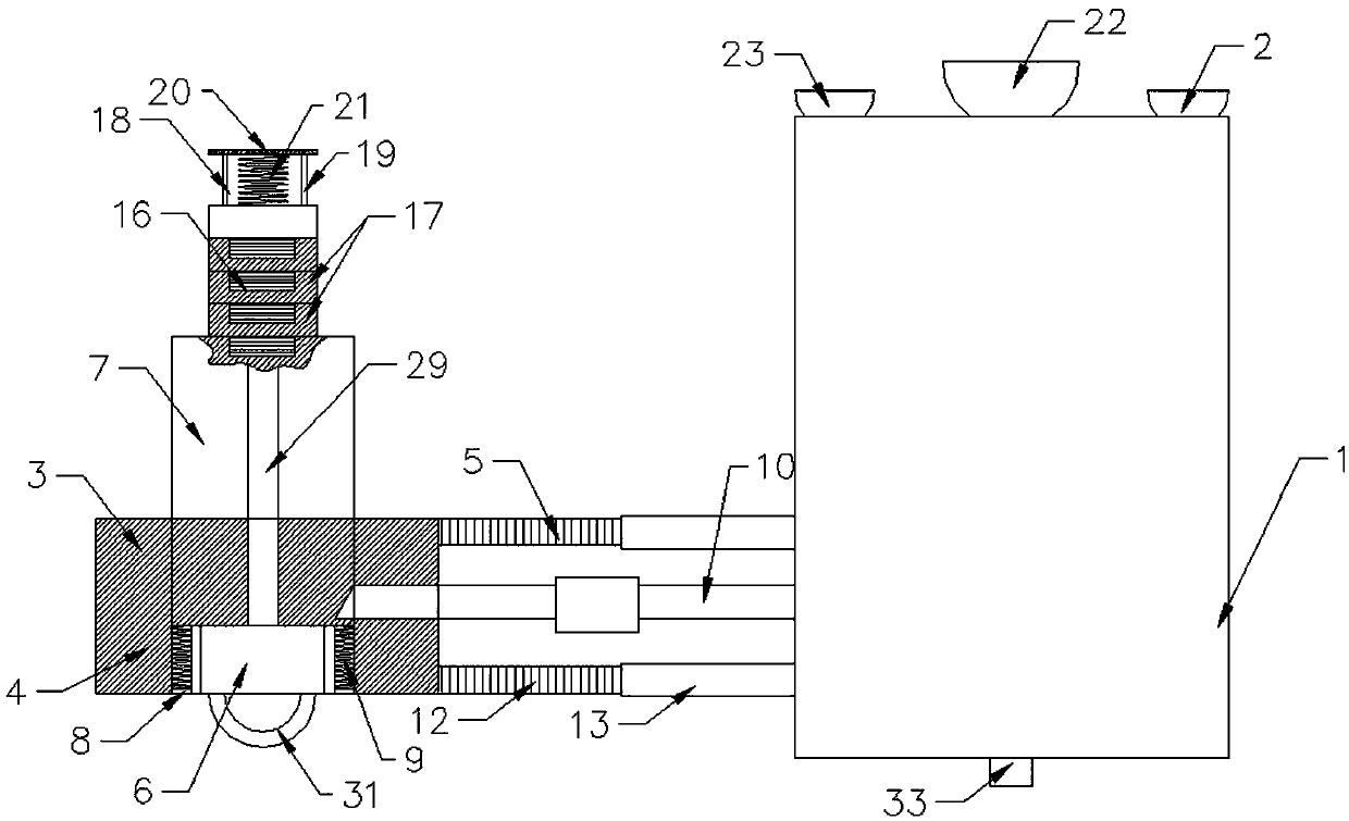
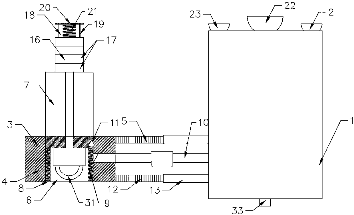
[0046] A new type of push-pull timing switch, comprising a timing switch body 1, the rear side of the timing switch body 1 is provided with a suction device 2 for connecting with a wall, and a switch device 3 is provided on one side of the timing switch body 1;

[0047] The switch device 3 includes a base 4, a connecting rod 5 is horizontally arranged between the base 4 and the time switch body 1, a through hole 6 is arranged inside the base 4, and the base 4 is located at the position of the through hole 6 and is provided with the through hole 6 Equipped with a push-pull rod 7, a circular baffle 8 is provided in the through hole 6 on the side of the base 4 away from the adsorption device 2, and a first spring 9 is provided between the baffle 8 and the push-pull rod 7;

[0048] A cross bar 10 is provided between the push-pull rod 7 and the timing switch body 1, and the timing switch body 1 controls the horizontal bar 10 to move in the horizontal direction; the push-pull rod 7 is pro...

Embodiment 2

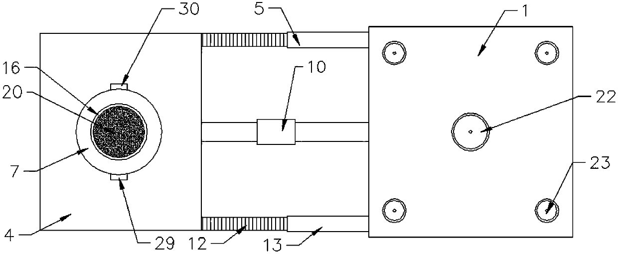
[0054] This embodiment is further optimized based on embodiment 1. The outer wall of the push-pull rod 7 is evenly distributed with a plurality of guide rods 29 parallel to the length of the push-pull rod 7, and the base 4 is provided with a guide groove 30 corresponding to the position of the guide rod 29, and the guide rod 29 The guide groove 30 can not only guide the push-pull rod 7 during the movement of the push-pull rod 7, but also prevent the push-pull rod 7 from rotating, and facilitate the connection of the groove 11 and the cross rod 10.

Embodiment 3

[0056] This embodiment is further optimized based on Embodiment 1. The push-pull rod 7 is provided with a pull ring 31 on the side of the first spring 9, so that the push-pull rod 7 can be easily stretched.


PUM


Abstract

The invention relates to the technical field of switches, and discloses a novel push-pull type time switch. The novel push-pull type time switch comprises a time switch body, an adsorption device anda switch device; the switch device includes a pedestal and a push-pull rod in the pedestal; a spring is arranged at a bottom of the push-pull rod; a transverse rod is arranged between the push-pull rod and the time switch body; the push-pull rod is provided with a groove corresponding to the transverse rod; a basic seat component is arranged on a top of the push-pull rod; the basic seat componentcomprises multiple basic seats arranged coaxially; and the multiple basic seats are in a threaded connection. According to the novel push-pull type time switch, the structure is simple, the cost is low, the novel push-pull type time switch can be used for controlling a plurality of equipment and the detachment is convenient; and through the basic seats, not only can a distance between the switch device and a switch in need of being controlled be adjusted conveniently, but also the basic seats and a buffer device can be replaced conveniently, and thus the pull-push rod is avoided to be replacedand the cost is saved.

Description

Technical field [0001] The invention relates to the technical field of switches, in particular to a new type of push-pull timing switch. Background technique [0002] At present, exhaust fans are installed in the toilets in urban houses to facilitate the exhaust of the odor in the toilets. However, most exhaust fans are manually switched, and people need to go in the toilet after a period of time. The exhaust fan is turned off, and people usually forget to turn off the exhaust fan after they are busy with other things after going to the toilet, which causes a waste of energy; since people usually go to bed directly after going to the toilet at night, they cannot open the exhaust fan at this time. The air fan has become a headache. If it is turned on, it can only be turned off in the morning, which will waste energy; if it is not turned on, when other people go to the bathroom, the smell in the bathroom will be sour and make others miserable; [0003] In addition, the existing hous...

Claims


Application Information

Patent Timeline
Patent Type & Authority Applications(China)
IPC IPC(8): H01H43/02H01H43/04
CPCH01H43/02H01H43/022H01H43/04
Inventor 雍海燕
Owner CHENGDU KECHUANGCHENG TECH
Why Eureka
Try Eureka