Optical element and display device

一种光学元件、显示装置的技术,应用在光学元件、光学、光导等方向,能够解决反射率下降等问题

Active Publication Date: 2018-04-03
SEIKO EPSON CORP
View PDF6 Cites 3 Cited by
  • Summary
  • Abstract
  • Description
  • Claims
  • Application Information

AI Technical Summary

Problems solved by technology

In Patent Document 2, as an example of the reflection characteristics of the selective reflection surface, it is described that the reflectance decreases as the incident angle of light increases.

Method used


Image

  • Optical element and display device
  • Optical element and display device
  • Optical element and display device

Examples


Embodiment Construction

[0026] Hereinafter, one embodiment of the present invention will be described with reference to the drawings.

[0027] The display device of this embodiment is used, for example, as a head-mounted display that is worn on the head of an observer and used.

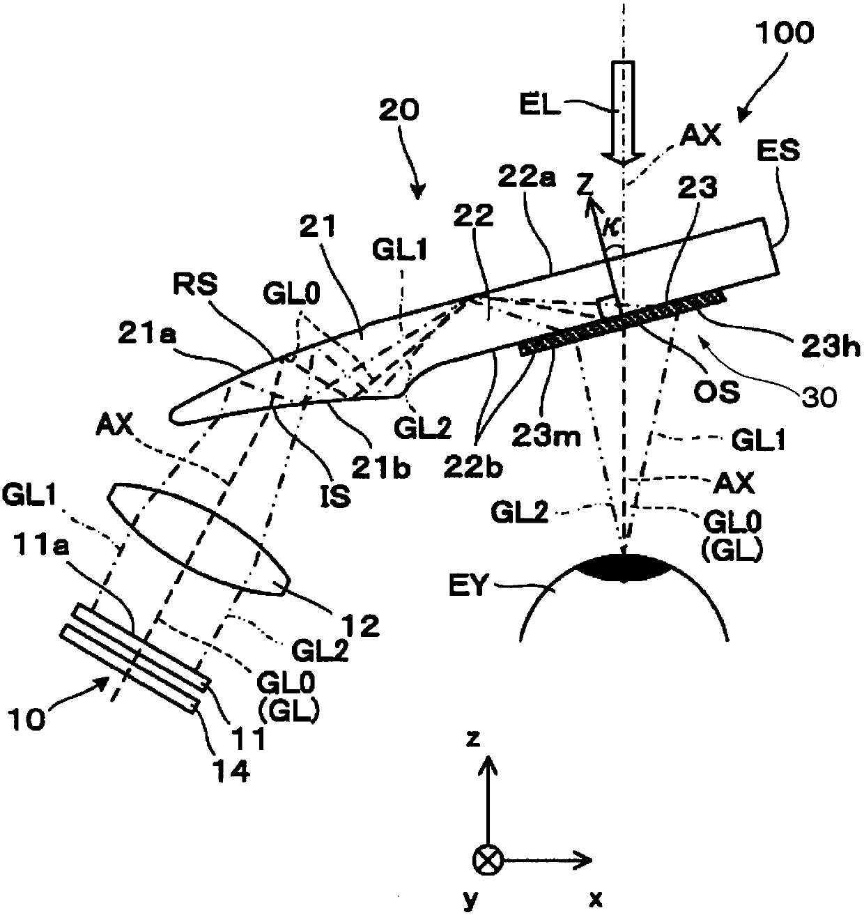
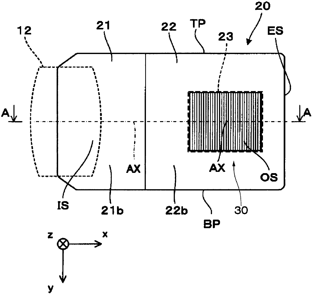
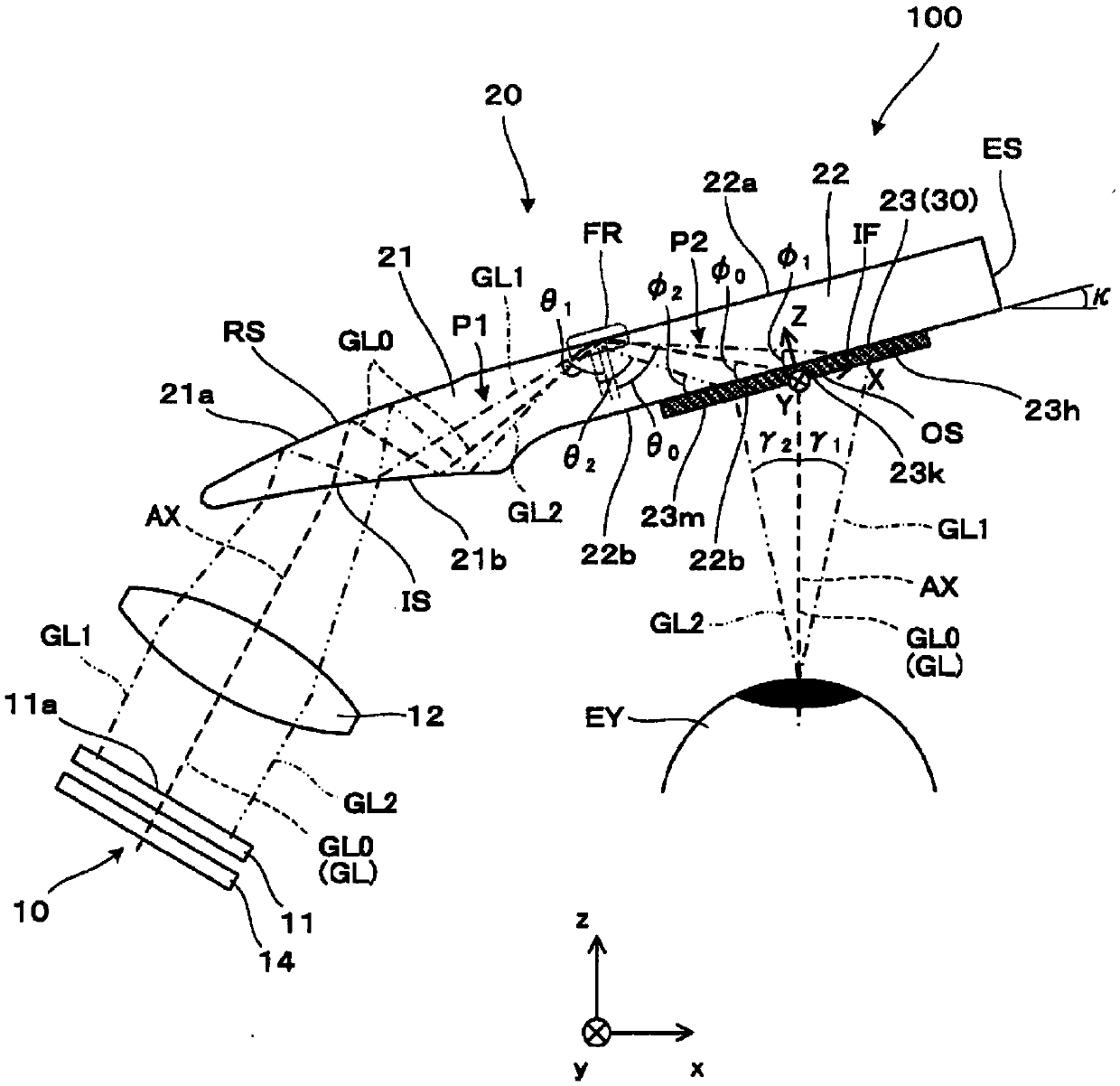
[0028] figure 1 It is a plan view of the display device of the embodiment. figure 2 It is a rear view of the light guide device viewed from the observer side. image 3 is a diagram showing the optical path of image light in the light guide device.

[0029] In each of the following drawings, in order to facilitate the observation of each constituent element, it may be shown on a different scale depending on the constituent element.

[0030] (Overall structure of light guide device and display device)

[0031] Such as figure 1 As shown, the display device 100 has an image forming device 10 and a light guide device 20 . figure 1 corresponds to figure 2 The A-A section of the light guide 20 is shown.

[0032] The displ...


PUM


Abstract

The invention provides an optical element and a display device capable of reducing leaks of image light to an opposite side of an observer after passes through a light guiding body. The optical element includes a plurality of partially reflecting mirrors provided in parallel to each other with an interval therebetween, and reflecting partial image light and external light and allowing the other part of the image light and external light to pass through, and a transmittance member interposed between adjacent two partially reflecting mirrors of the plurality of partially reflecting mirrors. Thetransmittance member has an incidence surface on which an image light and an external light are incident through a light guiding body, and an exit surface from which the image light and the external light are exited to an observer side. Each of the plurality of partially reflecting mirrors is disposed so as to be inclined with respect to the incidence surface and the exit surface, and a reflectance of light incident at a relatively small incidence angle with respect to surfaces of each partially reflecting mirror is lower than a reflectance of light incident at a relatively large incidence angle.

Description

technical field [0001] The present invention relates to an optical element and a display device. Background technique [0002] In recent years, as one of wearable information devices, an image display device of a type that is worn on the head of an observer and used, such as a head-mounted display, has been provided. Also known is a so-called see-through image display device that can simultaneously visually recognize both an image generated by a display element and an image of the outside world when the observer wears the image display device. [0003] Patent Document 1 below discloses a head-mounted display system including a substrate and a plurality of partial reflection surfaces provided inside the substrate. In this system, part of the light guided inside the substrate is reflected by the plurality of partially reflective surfaces and guided to the eyes of the observer. In Patent Document 1, as an example of the reflection characteristics of the partially reflecting s...

Claims


Application Information

Patent Timeline
Patent Type & Authority Applications(China)
IPC IPC(8): G02B27/01G02B6/00
CPCG02B6/00G02B27/0172G02B6/002G02B17/006G02B17/086G02B6/003G02B6/0055G02B2027/0125G02B2027/0178
Inventor 吉田昇平松木隼人
Owner SEIKO EPSON CORP
Why Eureka
Try Eureka