Stimulated polariton scattering optical amplifier

Inactive Publication Date: 2005-08-02
THE BOEING CO
View PDF7 Cites 6 Cited by
  • Summary
  • Abstract
  • Description
  • Claims
  • Application Information

AI Technical Summary

Benefits of technology

[0006]In a broad aspect, the stimulated polariton scattering optical amplifier of the present invention includes a first control optics assembly, a driver element, a second control optics assembly, a polariton active medium and egressing optics. The first control optics assembly receives an incoming laser beam and adjusts that incoming laser beam in accordance with first desired wavelength, polarization and beam propagation parameters. A driver element produces a driver laser beam. A second control optics assembly receives the driver laser beam and adjusts that driver laser beam in accordance with second desired wavelength, polarization and beam propagation parameters. A polariton active medium receives an output from the first control optics assembly and an output from the second control optics assembly. The polariton active medium provides a non-linear optical interaction between the outputs such that the incoming laser beam is amplified producing an amplified polariton active medium output laser beam and a depleted dr

Problems solved by technology

They do not address the use of the parametric gain for amplifying a signal.
Use of Raman scattering for optical signal amplification has limitations in its operation and implementation.
In m

Method used


Image

  • Stimulated polariton scattering optical amplifier
  • Stimulated polariton scattering optical amplifier
  • Stimulated polariton scattering optical amplifier

Examples


Example

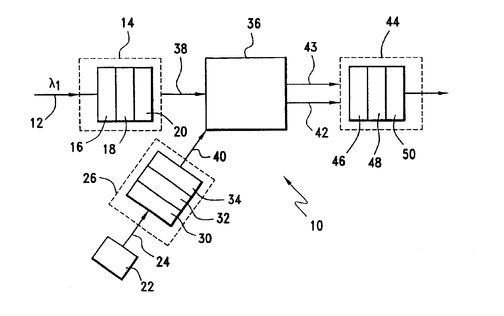
[0011]Referring to the drawings and the characters of reference marked thereon, FIG. 1 illustrates a preferred embodiment of the present invention, designated generally as 10. An incoming laser beam 12 is received by a first control optics assembly, designated generally as 14. The laser beam, λ1, may be generally described as an electromagnetic or light beam with a single narrow wavelength in the optical regime (0.1-10 microns), which is propagating in a uniform well-defined direction, made possible by its coherence properties. The laser beam could represent an image or could be a digitally encoded optical beam for data transmission.

[0012]The first control optics assembly 14 adjusts the incoming laser beam in accordance with desired wavelength, polarization and beam propagation parameters. These parameters can include, for example, precise wavelength filtering to the expected signal wavelength, the optical bandwidth of the incoming signal or the polarization of the light. The wavele...


PUM


Abstract

The stimulated polariton scattering optical amplifier includes a first control optics assembly, a driver element, a second control optics assembly, a polariton active medium and egressing optics. The first control optics assembly receives an incoming laser beam and adjusts that incoming laser beam in accordance with first desired wavelength, polarization and beam propagation parameters. A driver element produces a driver laser beam. A second control optics assembly receives the driver laser beam and adjusts that driver laser beam in accordance with second desired wavelength, polarization and beam propagation parameters. A polariton active medium receives an output from the first control optics assembly and an output from the second control optics assembly. The polariton active medium provides a non-linear optical interaction between the outputs such that the incoming laser beam is amplified, producing an amplified polariton active medium output laser beam and a depleted driver laser beam. Egressing optics receives the amplified polariton active medium output laser beam and the depleted driver laser beam. The egressing optics controllably transmits the amplified polariton active medium output laser beam in accordance with third desired wavelength, polarization, and beam propagation parameters and prevents transmission of the depleted driver laser beam. The output of the egressing optics includes an amplified egressing optics output laser beam.

Description

BACKGROUND OF THE INVENTION[0001]1. Field of the Invention[0002]This invention relates to optical amplifiers and more particularly to an optical amplifier that uses stimulated polariton scattering for providing optical amplification.[0003]2. Description of the Related Art[0004]Heretofore, the field of optical signal amplifiers has been dominated by Raman amplifiers. For example, U.S. Pat. No. 3,414,354, issued to E. H. Siegler Jr., entitled Raman Spectrometers, is a seminal publication disclosing the use of stimulated Raman scattering, to provide optical amplification. In a later example, U.S. Pat. No. 3,515,897, issued to W. H. Culver, entitled Stimulated Raman Parametric Amplifier, discloses a design for implementing stimulated Raman scattering for amplification. In Physical Review 112, p. 1555-1567 (1958), J. J. Hopfield discusses the effect of exciton absorption on the dielectric response within a crystal. This affects the crystal polariton behavior. The date of the Hopfield pap...

Claims


Application Information

Patent Timeline
IPC IPC(8): H01S3/00H01S3/30
CPCH01S3/30H01S3/302
Inventor HUNT, JEFFREY H.ATMUR, ROBERT J.
Owner THE BOEING CO
Why Eureka
Try Eureka