Steel sleeve rotating-type locking mechanism

A locking mechanism and rotary technology, applied in the connection of connecting components, mechanical equipment, rods, etc., can solve the problems of inconvenient operation, uneven force, etc., to improve the connection speed and strength, uniform force, improve The effect of compression strength

Pending Publication Date: 2018-04-13
郑州宇恒环保技术有限公司
View PDF0 Cites 1 Cited by
  • Summary
  • Abstract
  • Description
  • Claims
  • Application Information

AI Technical Summary

Problems solved by technology

[0003] The present invention aims at the problems of uneven stress and inconvenient operation in existing locking mechanisms c

Method used


Image

  • Steel sleeve rotating-type locking mechanism
  • Steel sleeve rotating-type locking mechanism

Examples


Embodiment 1

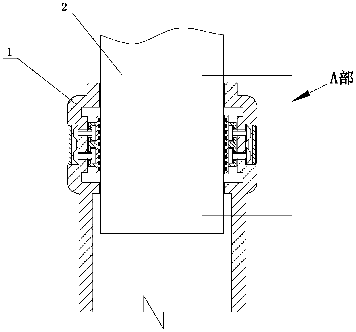
[0012] Embodiment 1: as figure 1 The steel casing rotary locking mechanism shown is located between the outer casing 1 and the inner casing 2 which are fitted together. An annular concave groove is arranged on the side wall of the outer sleeve 1 , and there are even a pair of adjusting and pressing components symmetrically on the inner wall 301 of the annular concave groove. Both sides adjust and hold down the assembly structure identically.

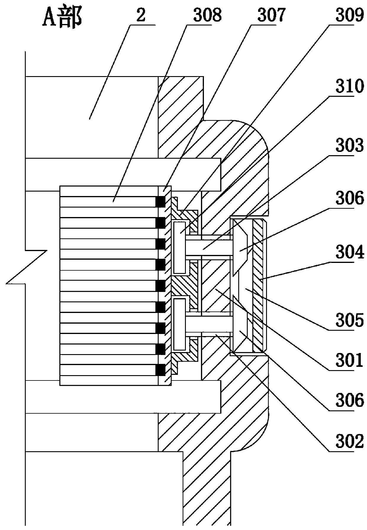
[0013] For the specific structure of adjusting the pressing assembly, see figure 2 As shown, it includes an arc-shaped pressing tile 307 matching the side of the inner casing 2 and a pair of adjusting bolts 303 with opposite thread directions. A pair of adjusting bolts 303 is movably connected with the back of the arc-shaped pressing tile 307 . A pair of screw holes 302 with opposite helical directions are formed on the inner wall 301 of the annular recess, and the pair of adjusting bolts 303 are matched and installed in the correspo...

Embodiment 2

[0019] Embodiment 2: On the basis of Embodiment 1, an adjusting ring 304 is set on the outside of the annular recessed groove, and the side wall of the outer sleeve 1 outside the annular recessed groove is provided with annular convex and concave moldings respectively on the inner wall of the adjusting ring 304, The side wall of the outer casing 1 and the inner wall of the adjustment ring 304 are embedded with each other by matching annular convex and concave moldings. And a gap is set between adjacent annular convex and concave fillets and a sealing ring is set. Improve the sealing performance to the adjustment parts.


PUM


Abstract

The invention discloses a steel sleeve rotating-type locking mechanism. An annular sunken groove is formed in the side wall of an outer sleeve, and a pair of adjusting pressing assemblies are at leastsymmetrically arranged on the inner wall of the annular sunken groove; a fixing sleeve is arranged on the back side of an arc-shaped pressing tile piece, the fixing sleeve is provided with an inner cavity, and an upper through hole and a lower through hole are formed in the side wall of the inner cavity; a pair of adjusting bolts are mounted in the upper through hole and the lower through hole ina sleeved mode correspondingly, and bevel gears are arranged at the outer ends, located at the screw hole outer section, of the pair of adjusting bolts correspondingly; and the inner side or the outer side of the annular sunken groove is sleeved with an adjusting ring, a conical gear ring is arranged at the middle of the inner side of the adjusting ring, and the conical gear ring is simultaneously engaged with a bevel gear of the pair of the adjusting bolts. The steel sleeve rotating-type locking mechanism realizes quick pressing or releasing of an inner sleeve, and the purpose of improving the connecting speed and the strength is achieved. Not only can horizontal moving of the arc-shaped pressing tile piece be ensured, but also the fine-adjusting state can provide the large enough jacking and pressing force, and automatic reverse moving does not occur.

Description

Technical field: [0001] The invention relates to the technical field of connection and locking of steel structure sleeves, in particular to a rotating locking mechanism for steel sleeves. Background technique: [0002] It is very common to connect and lock the inner and outer sleeves. For example, the assembly of various brackets on construction sites or industrial production frames, and the connection of some precision equipment, etc., all involve the locking of sleeves. The existing structural way of socketing steel pipes is either fixed by the corresponding cross buckle, or a locking pin is provided on the corresponding part, or locked by strong pressing of an eccentric handle with a pin shaft. However, the existing structural methods for socketing steel pipes generally have the problem of poor strength of the connection parts, which affects the stability of the connection bracket. For example, although fast locking can be realized by the locking pin, the locking pin can...

Claims


Application Information

Patent Timeline
IPC IPC(8): F16B7/18F16B7/08
CPCF16B7/00F16B7/182
Inventor 付玉杰
Owner 郑州宇恒环保技术有限公司
Why Eureka
Try Eureka