A deceleration roadblock for controlling one-way driving of automobiles
What is Al technical title?
Al technical title is built by PatSnap Al team. It summarizes the technical point description of the patent document.
A technology for one-way driving and deceleration roadblocks, which is applied in the field of traffic speed limiting devices and deceleration roadblocks, which can solve the problems such as the surge of road traffic flow, the inability to restrict vehicles from one-way driving, and endangering the safety of others
Active Publication Date: 2020-04-28
惠安恒久升电子科技有限公司
View PDF7 Cites 0 Cited by
Summary
Abstract
Description
Claims
Application Information
AI Technical Summary
This helps you quickly interpret patents by identifying the three key elements:
Problems solved by technology
Method used
Benefits of technology
Problems solved by technology
[0002] With the improvement of people's living standards, more and more people own their own cars, which leads to a sharp increase in road traffic. At the same time, some people like to speed, especially in densely populated places such as schools and communities, where traffic is extremely prone to occur. accident, endangering the safety of others
In addition, one-way driving is set in many road sections to relieve traffic pressure, but due to people's unconsciousness, there will be a phenomenon of violating traffic rules and driving in the opposite direction, which is prone to traffic accidents
The existing deceleration roadblocks can effectively reduce the speed of vehicles, but cannot restrict the one-way driving of vehicles
Method used
Image
Click on the blue label to locate the original text in one second.
Reading with bidirectional positioning of images and text.
Examples
Embodiment Construction
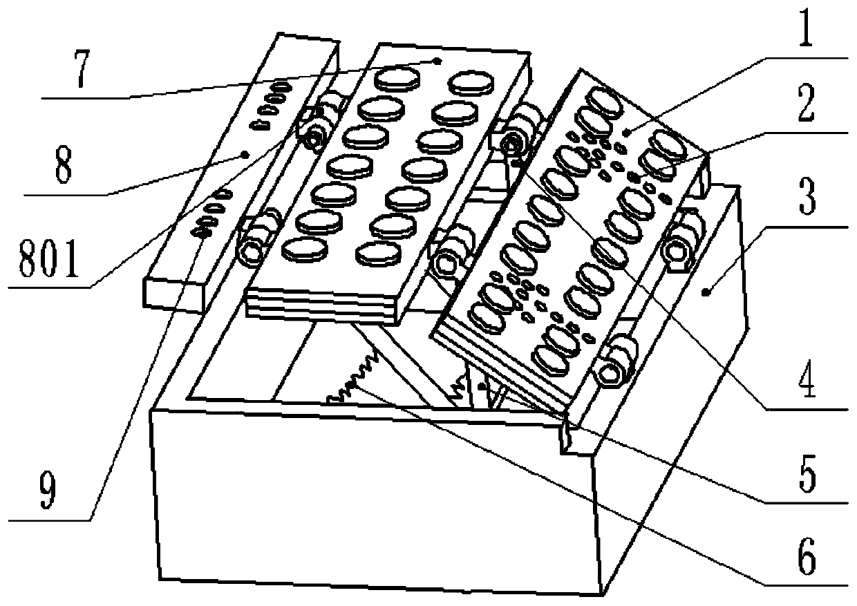
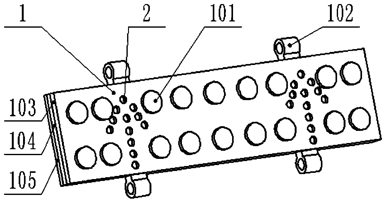
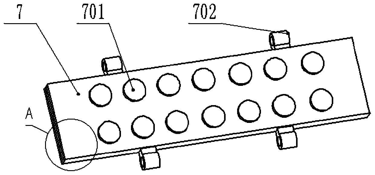
[0008] A deceleration roadblock for controlling one-way driving of a car, which is composed of a front plate 1, a cylindrical bump 101, a connecting piece 102, tempered glass 103, a solar power generation panel 104, a metal plate 105, a green LED light tube 2, a box body 3, Connecting plate 301, connecting piece 302, limit baffle 303, positioning block 304, movable rod 4, cylinder 5, compression spring 6, horizontal plate 7, cylindrical bump 701, connecting piece 702, tempered glass 703, solar power Plate 704, metal plate 705, suspended plate 8, connecting piece 801, red LED lamp 9, wire 10, battery 11 and spring 12, the front plate 1 has a three-layer structure, and is characterized in that it includes tempered glass 103, The solar power generation panel 104, the metal plate 105, the toughened glass 103 is on the uppermost layer, the solar power generation panel 104 is located between the toughened glass 103 and the metal plate 105, the three are closely attached, and there is...
PUM
Abstract
The invention relates to a speed bump for controlling one-way running of cars and belongs to the field of traffic facilities. The speed bump is composed of a front plate, a first cylindrical protrusion, a first connector, first tempered glass, a first solar power generating plate, a metal plate, a green LED lamp, a box body, a connecting plate, a second connector, a limiting baffle, locating blocks, movable rods, drums, compressed springs, a transverse plate, a second cylindrical protrusion, a third connector, second tempered glass, a second solar power generating plate, a second metal plate,a suspended plate, a connecting structure, a red LED lamp, wires, springs and a storage battery; the solar power generating plates can generate power to supply energy to the LED lamps, and when the length of the compressed springs stays at the original state, the front plate and the transverse plate support the suspended plate; the speed bump can be automatically closed when ground by a car and then automatically recover to the original shape after the car leaves; when the car runs inversely, the drums can be tightly fitted to the limiting baffle to make the limiting baffle unable to rotate inversely, correspondingly the front plate and the transverse plate cannot be closed, and therefore the car is prevented from running inversely. The speed bump can achieve great automation and effectively reduce the occurrence probability of inverse running of cars.
Description
technical field [0001] The invention relates to a deceleration roadblock for controlling one-way driving of automobiles, specifically a traffic speed limiting device which adopts the structure of a box body and a limit baffle and is equipped with a movable movable plate, and belongs to the field of traffic facilities. Background technique [0002] With the improvement of people's living standards, more and more people own their own cars, which leads to a sharp increase in road traffic. At the same time, some people like to speed, especially in densely populated places such as schools and communities, where traffic is extremely prone to occur. Accidents that endanger the safety of others. In addition, one-way driving is set in many road sections to relieve traffic pressure, but due to people's unconsciousness, there will be a phenomenon of violating traffic rules and driving in the opposite direction, which is prone to traffic accidents. Existing deceleration roadblocks can ...
Claims
Application Information
Patent Timeline
Application Date:The date an application was filed.
Publication Date:The date a patent or application was officially published.
First Publication Date:The earliest publication date of a patent with the same application number.
Issue Date:Publication date of the patent grant document.
PCT Entry Date:The Entry date of PCT National Phase.
Estimated Expiry Date:The statutory expiry date of a patent right according to the Patent Law, and it is the longest term of protection that the patent right can achieve without the termination of the patent right due to other reasons(Term extension factor has been taken into account ).
Invalid Date:Actual expiry date is based on effective date or publication date of legal transaction data of invalid patent.