Concealed joints for components of furniture and decorative objects

A technology for joining devices and decorations, which is applied to furniture parts, furniture connections, home appliances, etc., and can solve problems such as no appearance, obstacles, etc.

Active Publication Date: 2021-06-04
LEONARDO
View PDF13 Cites 0 Cited by
  • Summary
  • Abstract
  • Description
  • Claims
  • Application Information

AI Technical Summary

Problems solved by technology

[0032] However, this further solution also suffers from the same problems associated with the large number of holes of the mostly visible engagement means and the corresponding cover, namely not having an aesthetically strong appearance and producing the previously mentioned obstructions and weakenings.

Method used


Image

  • Concealed joints for components of furniture and decorative objects
  • Concealed joints for components of furniture and decorative objects
  • Concealed joints for components of furniture and decorative objects

Examples


Embodiment Construction

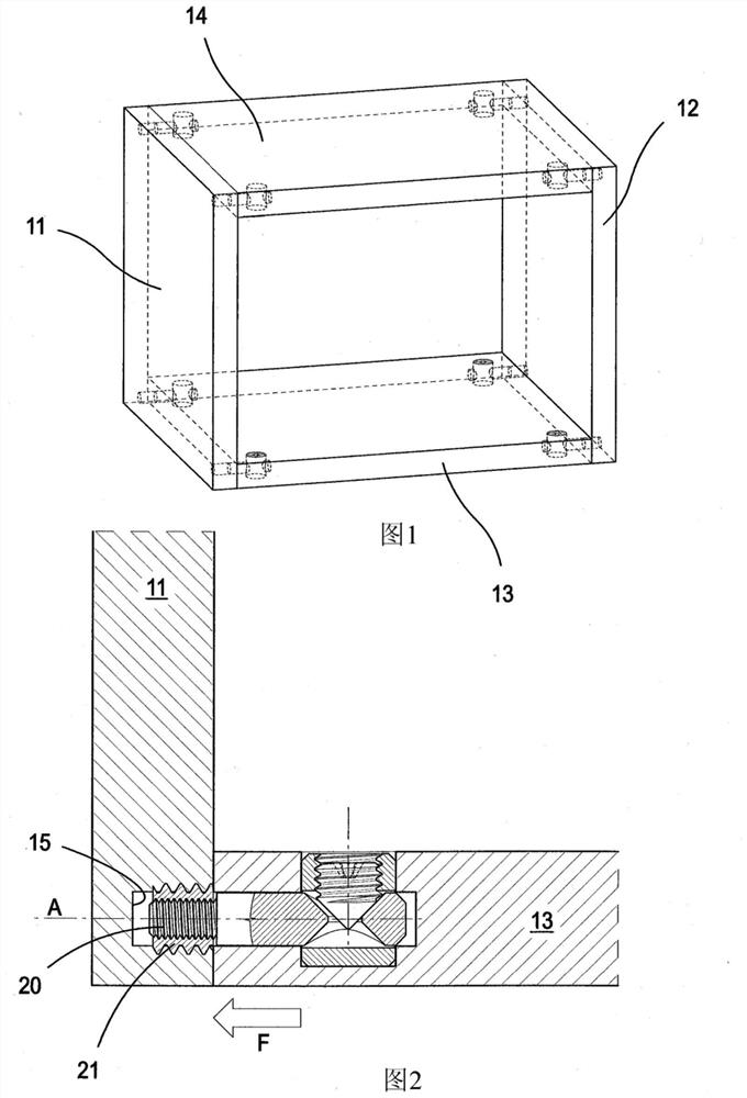
[0056] First refer to Figure 7 to Figure 13 , these figures show a first embodiment of the joining device for parts of furniture and upholstery according to the invention. In this example, the joining means must connect and join a first panel 11 such as a shoulder of a piece of furniture with a second panel 12 such as a bottom 12 or also a different panel or a shelf part or a top, as shown in the figure. Show. In particular, they must be moved towards each other in the approach direction (d) in order to bring the edge (B) of one plate against the surface (S) of the other plate in the fastened position.

[0057] As shown in the example, the first plate 11 and the second plate 12 are generally perpendicular to each other, but they may also be inclined relative to each other.

[0058] In this non-limiting example, the second plate or bottom 12 comprises: near one of its end sides (positioned perpendicular to the rear of the furniture when assembled), a seat S1 for locking the ...


PUM


Abstract

A concealed joining device for parts of furniture and upholstery, especially for use between a first panel (11) such as the shoulder of a piece of furniture and a second panel (12) such as the bottom or Between the shelf section or top, the first and second boards must be moved towards each other in the approach direction (d) so that the edge (B) of one board rests against the surface (S) of the other board in the fastened position On said joint means consisting of a locking group (GB) and a connection group (GC) assembled on said plates (11, 12), characterized in that said locking group (GB) inserts a In the seat (S1, S1') in the thickness (SP) of the plate (11,12) of said locking group (GB), said seat (S1, S1') having an axis perpendicular to said direction (d) (X) and extending from the rear edge (B1) of said plates (11,12) towards the interior of said plates (11,12), forming a single visible hole (30) in both plates when connected .

Description

technical field [0001] The invention relates to a concealed joining device for parts of furniture and upholstery. Background technique [0002] The joining of two panels, for example between the shoulder and the bottom, or also the shelf, of a piece of furniture is currently performed in various ways and in different solutions in the field of furniture and furnishing. [0003] Examples of such solutions are known from patents US7494297, US5567081, US6547477 and US4408923. [0004] These known technical solutions have a certain complexity and also a certain visibility, since they require closure elements for positioning the seats or holes necessary for the elements to effect the engagement. [0005] in this regard, Figure 1 to Figure 6 Some known solutions for joining means for parts of furniture or upholstery are shown, for example between a shoulder and a bottom, but also a conventional shelf or top, of a piece of furniture. [0006] exist figure 1 and figure 2 In th...

Claims


Application Information

Patent Timeline
Patent Type & Authority Patents(China)
IPC IPC(8): F16B12/20F16B12/46
CPCA47B96/066F16B12/46F16B12/2063
Inventor 卡洛·卡塔内奥
Owner LEONARDO
Why Eureka
Try Eureka