Quick stamping die

A technology of stamping dies and molds, which is applied in the field of rapid stamping dies and can solve problems such as time-consuming

Inactive Publication Date: 2018-05-18
宁波江北珂达汽车技术有限公司
View PDF7 Cites 0 Cited by
  • Summary
  • Abstract
  • Description
  • Claims
  • Application Information

AI Technical Summary

Problems solved by technology

[0004] The purpose of the present invention is to provide a rapid stamping die to solve the need to pick and place workpieces in the prior art, and it takes a lot of time to reposition the workpieces

Method used


Image

  • Quick stamping die
  • Quick stamping die

Examples


Embodiment Construction

[0017] The present invention will be described in further detail below by means of specific embodiments:

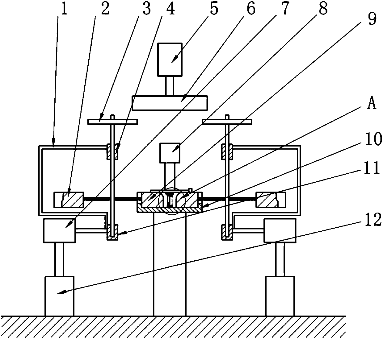
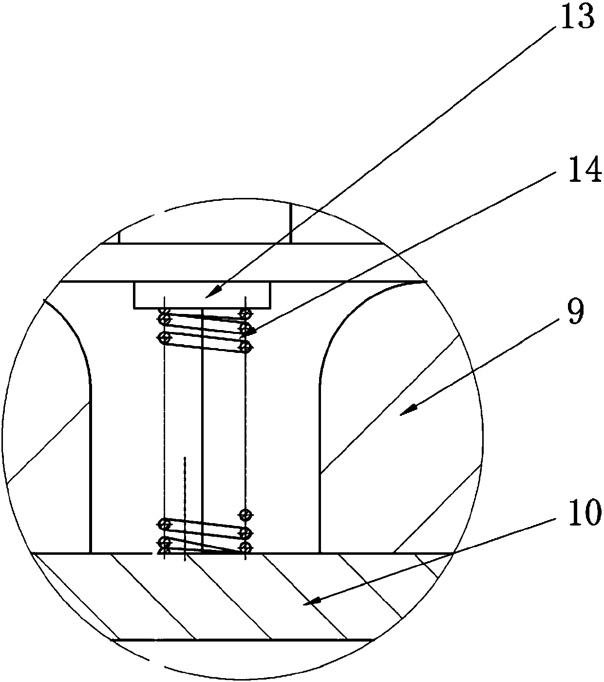
[0018] The reference signs in the drawings of the description include: the third connecting rod 1, the second half mold 2, the driven gear 3, the balance sleeve 4, the rotating motor 5, the driving gear 6, the push cylinder 7, the stamping cylinder 8, the first half Die 9, stamping platform 10, fixed sleeve 11, lifting cylinder 12, stripping plate 13, stripping spring 14.

[0019] Embodiment: the rapid stamping die in this scheme, as figure 1 and figure 2 As shown, it includes a mold lifting mechanism, a rotating mechanism and a stamping mechanism. The stamping mechanism includes a frame and a stamping cylinder 8. A vertical stamping platform 10 is fixedly connected to the frame. The free end of the stripping spring 14 is fixedly connected with the stripping plate 13, and the stripping plate 13 is located directly below the output end of the stamping cylinder 8, and th...


PUM


Abstract

The invention belongs to the field of stamping dies, and particularly discloses a quick stamping die. According to the main scheme, a rack is fixedly connected with a vertical stamping platform, the stamping platform is fixedly connected with a material returning spring, the free end of the material returning spring is fixedly connected with a material returning plate, and the material returning plate is located under the output end of a stamping air cylinder; a rotating shaft is rotationally connected into a fixed sleeve, the rotating shaft is fixedly connected with a first connecting rod anda second connecting rod, the first connecting rod and the second connecting rod are symmetrical with respect to the rotating shaft, the free end of the first connecting rod is fixedly connected to afirst semi-die, the free end of the second connecting rod is fixedly connected to a second semi-die, a lifting air cylinder is fixed to the rack, the output end of the lifting air cylinder is fixedlyconnected with a pushing air cylinder, and a piston rod of the pushing air cylinder is fixedly connected to the fixed sleeve; and the output end of a rotating motor is connected with a driving gear, and the output end of the motor and the output end of the stamping air cylinder are coaxial. The quick stamping die solves the problems that in the prior art, workpieces need to be taken and placed, and re-positioning of the workpieces consumes a lot of time.

Description

technical field [0001] The invention belongs to the field of stamping dies, in particular to a rapid stamping die. Background technique [0002] The process of manufacturing stepped cylindrical parts with medium and thick plates is relatively complicated, generally four or more steps are required, and four or more sets of molds are required, and each set of molds is very complicated, especially The punching pattern of the punching die used in the punching step is complicated, which affects the quality of the part and reduces the life of the die. In addition, the overall assembly of the existing mold is very difficult, the manufacturing and maintenance costs of the mold are high, but the production efficiency of the mold is very low, so it is urgent to improve. [0003] The patent document with the authorized announcement number CN101767154B discloses a rapid stamping die, which is composed of three pairs of dies: a primary stretching die, a stretching shaping die and a punc...

Claims


Application Information

Patent Timeline
IPC IPC(8): B21D22/06B21D37/10
CPCB21D22/06B21D37/10
Inventor 王健
Owner 宁波江北珂达汽车技术有限公司
Why Eureka
Try Eureka