Automatic clipping machine for pipe fitting joint sprue

A technology for shearing machines and pipe fittings, which is applied in the field of automatic shearing machines for pipe joint gates, can solve the problems of low shearing operation efficiency and achieve high gate shearing efficiency

Pending Publication Date: 2018-05-18
台州市黄岩奇泓智能科技有限公司
View PDF0 Cites 3 Cited by
  • Summary
  • Abstract
  • Description
  • Claims
  • Application Information

AI Technical Summary

Problems solved by technology

[0004] Traditionally, for the above-mentioned type of pipe joint a, after the injection molding is completed, the operator holds the pipe joint a with one hand and holds scissors with the other hand, and uses the scissors to cut off the position of the gate d one by one, so that the sleeve c can be removed from the pipe connector a, but follow the attached figure 1 For the pipe joint a shown, the operator needs to perform 16 shearing operations on a single pipe joint a, and the efficiency of the shearing operation is extremely low

Method used


Image

  • Automatic clipping machine for pipe fitting joint sprue
  • Automatic clipping machine for pipe fitting joint sprue
  • Automatic clipping machine for pipe fitting joint sprue

Examples


Embodiment Construction

[0036] The present invention will be further described in detail below in conjunction with the drawings.

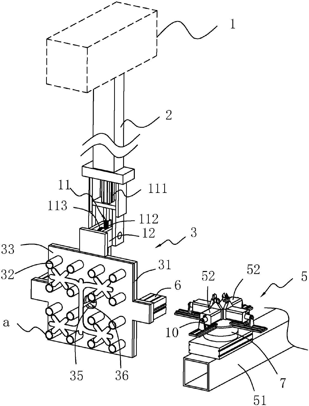
[0037] An automatic cutting machine for the sprue of pipe fittings, see figure 2 , Including a driving source 1, a moving arm 2, the driving source 1 is installed on an external beam, the moving arm 2 is arranged vertically downward, and the driving source 1 can drive the moving arm 2 to move back and forth, up and down, and left and right.

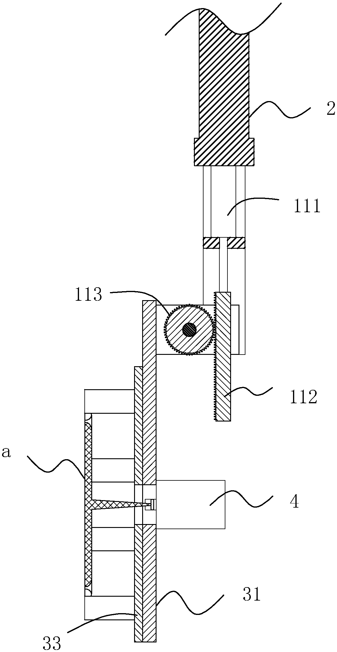
[0038] See figure 2 as well as image 3 , The lower end of the mobile arm 2 is provided with a flip arm 12 and a flip drive 11, the flip arm 12 is hinged to the lower end of the mobile arm 2, the hinge shaft is fixedly connected to the flip arm 12, the hinge between the flip arm 12 and the mobile arm 2 The axis of the shaft is arranged horizontally. The turning drive unit 11 includes a turning cylinder 111 mounted on the moving arm 2. The telescopic direction of the turning cylinder 111 is vertical. The telescopic end of the turning cyli...


PUM


Abstract

The invention discloses an automatic clipping machine for a pipe fitting joint sprue. According to the main points of the technical scheme, the automatic clipping machine comprises a drive source anda movable arm. The drive source is used for driving the movable arm to move. A transport mechanism is installed on the movable arm and comprises a transport plate connected to the movable arm. The transport plate is provided with a plurality of convex columns which are inserted in pipe sleeves correspondingly. A shearing mechanism is further included and comprises a holding frame and pneumatic scissors installed on the holding frame. The pneumatic scissors are used for clip the sprue of a pipe fitting joint on the transport mechanism. When injection molding of the pipe fitting joint is completed by a mold in an injection molding machine, through mutual matching of the pneumatic scissors and the movable arm, work of clipping of the sprue on the pipe fitting joint is completed, and clippingefficiency is high.

Description

Technical field [0001] The invention relates to a shearing machine, in particular to an automatic shearing machine for the sprue of a pipe fitting joint. Background technique [0002] The structure of the pipe fitting a usually injected by the injection mold is as attached figure 1 As shown, it includes a main runner b, a branch e, and a number of pipe sleeves c. The several pipe sleeves c are in a rectangular array. The main runner b is located in the middle of the several pipe sleeves c. The length direction of the main runner b and the pipe The length direction of the sleeve c is kept consistent, the runner e is connected to the end of the main runner b, and a gate d is connected between the runner e and the pipe sleeve c. [0003] As attached figure 1 The number of pipe fittings a shown is 16, each four is divided into one group, a total of four groups, the pipe sleeves c in each group of pipe fittings a are in a rectangular array, and each group of pipe fittings a corresponds ...

Claims


Application Information

Patent Timeline
Patent Type & Authority Applications(China)
IPC IPC(8): B29C45/38
CPCB29C45/382
Inventor 谢良富
Owner 台州市黄岩奇泓智能科技有限公司
Why Eureka
Try Eureka