Mechanical locking device for hydraulic supporting legs

A hydraulic outrigger and mechanical locking technology, which is applied in the field of hydraulic machinery, can solve the problems of oil leakage, low locking force, and low reliability, and achieve high load bearing, low rotational torque, and high safety and reliability. Effect

Active Publication Date: 2018-05-22
BEIJING XINLI MACHINERY
View PDF10 Cites 1 Cited by
  • Summary
  • Abstract
  • Description
  • Claims
  • Application Information

AI Technical Summary

Problems solved by technology

Hydraulic locking, that is, by installing a hydraulic lock to prevent oil backflow, this method is easy to implement, but due to internal and external leakage of oil, it is only suitable for short-term locking conditions
Mechanical locking, one is to achieve locking through the friction between the brake pads, locking sleeves and other locking devices and the piston rod. This method can achieve locking at any stroke, but the locking force is not large and the reliability is not high. ; One is to lock the piston rod through structures such as bolts and pads. This method has a simple structure and is only used for mechanical locking with a fixed stroke.

Method used


Image

  • Mechanical locking device for hydraulic supporting legs
  • Mechanical locking device for hydraulic supporting legs
  • Mechanical locking device for hydraulic supporting legs

Examples


Embodiment Construction

[0021] The preferred embodiments of the present invention will be described below in conjunction with the accompanying drawings. It should be understood that the preferred embodiments described here are only used to illustrate and explain the present invention, and are not intended to limit the present invention.

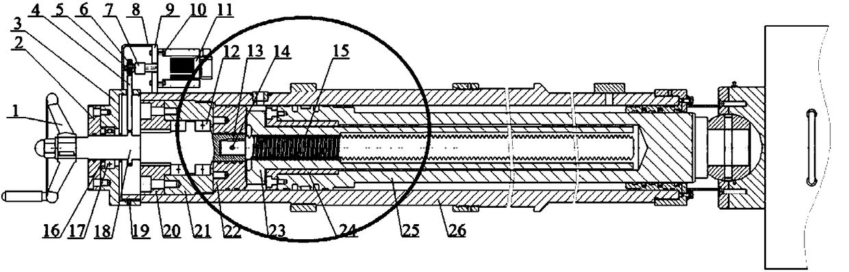
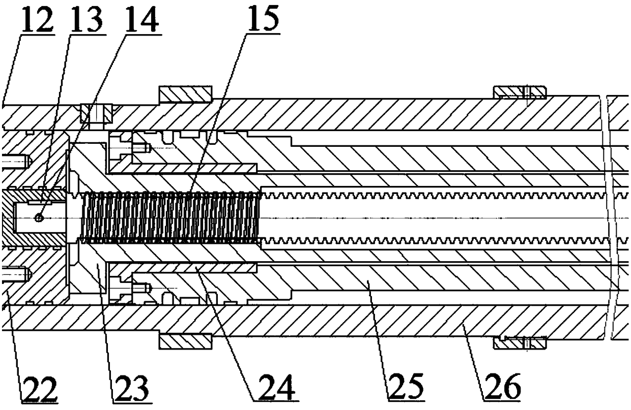
[0022] Such as figure 1 As shown, a mechanical locking device for hydraulic outriggers includes a hydraulic cylinder body 26, a sliding screw transmission mechanism arranged inside the hydraulic cylinder body 26, and a rotating support mechanism arranged inside the hydraulic cylinder body 26 and linked with the sliding screw transmission mechanism And a manual driving mechanism or an automatic driving mechanism for providing power to the rotating support mechanism. Under the action of the manual driving mechanism or the automatic driving mechanism, the rotating supporting mechanism drives the sliding screw transmission mechanism to move to a predetermined position to...


PUM


Abstract

The invention discloses a mechanical locking device for hydraulic supporting legs. The mechanical locking device comprises a hydraulic cylinder body, a sliding spiral transmission mechanism arranged in the hydraulic cylinder body, a rotating supporting mechanism arranged in the hydraulic cylinder body and connected with the sliding spiral transmission mechanism, and a manual driving mechanism or an automatic driving mechanism which provides power for the rotating supporting mechanism. Under the effect of the manual driving mechanism or the automatic driving mechanism, the rotating supporting mechanism drives the sliding spiral transmission mechanism to move to the predetermined position so as to achieve locking or unlocking of the hydraulic supporting legs.

Description

technical field [0001] The invention belongs to the technical field of hydraulic machinery, in particular to a mechanical locking device for hydraulic outriggers suitable for special vehicles or workbenches. Background technique [0002] Hydraulic outriggers are an important part of special vehicle operations, and play the role of platform leveling and support. In order to ensure the safety and reliability of long-term operation of special vehicles, the problem of retraction of hydraulic outriggers should be avoided. At present, the locking methods of hydraulic outriggers include hydraulic locking and mechanical locking. Hydraulic locking, that is, by installing a hydraulic lock to prevent oil backflow, this method is easy to implement, but due to internal and external oil leakage, it is only suitable for short-term locking conditions. Mechanical locking, one is to achieve locking through the friction between the brake pads, locking sleeves and other locking devices and th...

Claims


Application Information

Patent Timeline
Patent Type & Authority Applications(China)
IPC IPC(8): F15B15/26B60S9/10
Inventor 杨希英王立勇刘霄亮马鹤坤胡可狄
Owner BEIJING XINLI MACHINERY
Why Eureka
Try Eureka