
Coiled tubing drilling machine roller transport vehicle

A coiled tube and transport vehicle technology, which is applied in the direction of article transport vehicles, motor vehicles, transport objects, etc., can solve the problems of affecting the sinking amount of the drum, difficult to meet the conditions, and the capacity of the drum cannot be increased, so as to improve the capacity of the coiled tube. Effect

Active Publication Date: 2018-05-29
BC P INC CHINA NAT PETROLEUM CORP +3
View PDF6 Cites 0 Cited by
  • Summary
  • Abstract
  • Description
  • Claims
  • Application Information

AI Technical Summary

Problems solved by technology

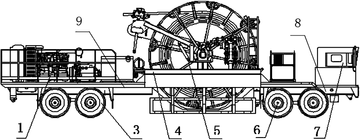
Coiled tubing drilling requires large-diameter and long-sized coiled tubing, which leads to the continuous increase in the size of the coiled tubing rig drum, making it difficult to transport the coiled tubing rig drum
[0003] At present, the conventional second-class chassis vehicles, the engine is basically the front, and the power is transmitted to the rear axle through the transmission shaft. Due to the existence of the transmission shaft, the sinking of the drum is affected, and the capacity of the drum cannot be increased; while the semi-trailer is used to transport the drum , although the capacity of the drum can be increased as much as possible, but due to the self-limitation of the climbing performance and turning radius of the semi-trailer, it is often difficult to meet the conditions of the oil field roads in hilly and mountainous areas.

Method used


Image

  • Coiled tubing drilling machine roller transport vehicle
  • Coiled tubing drilling machine roller transport vehicle
  • Coiled tubing drilling machine roller transport vehicle

Examples


Embodiment Construction

[0030] The details of the present invention can be understood more clearly with reference to the accompanying drawings and the description of specific embodiments of the present invention. However, the specific embodiments of the present invention described here are only for the purpose of explaining the present invention, and should not be construed as limiting the present invention in any way. Under the teaching of the present invention, the skilled person can conceive any possible modification based on the present invention, and these should be regarded as belonging to the scope of the present invention. It should be noted that when an element is referred to as being “disposed on” another element, it may be directly on the other element or there may also be an intervening element. When an element is referred to as being "connected to" another element, it can be directly connected to the other element or intervening elements may also be present. The terms "mounted", "connec...


PUM


Abstract

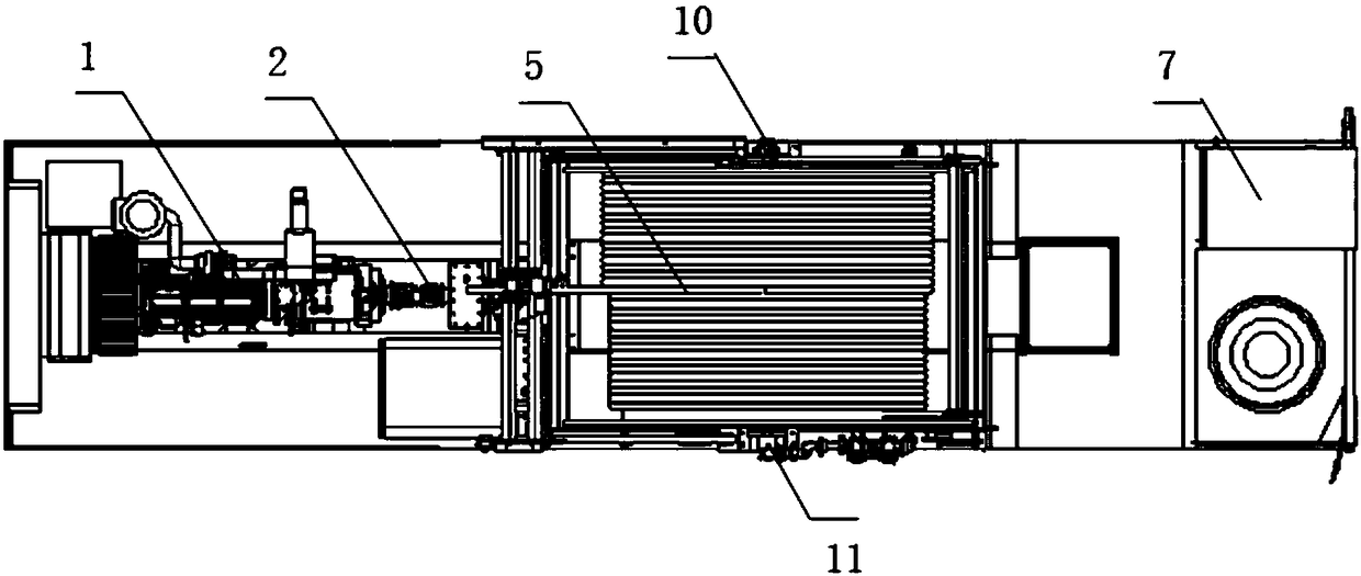
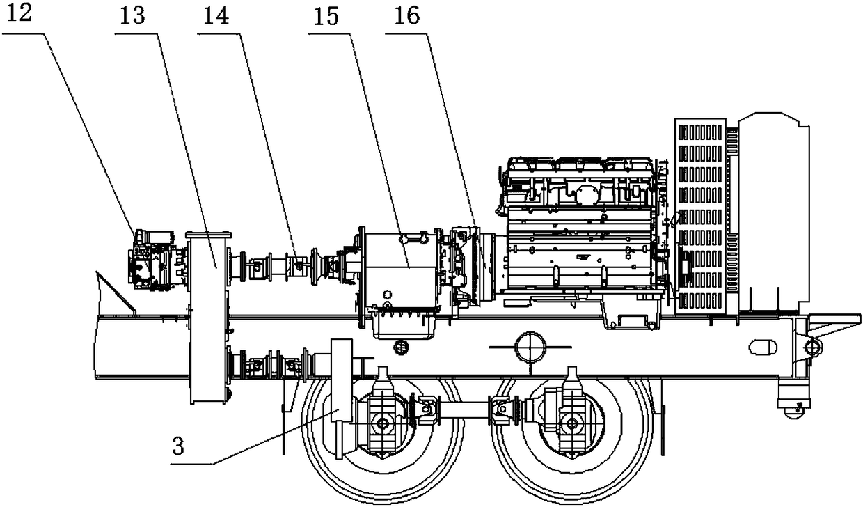
The invention discloses a coiled tubing drilling machine roller transport vehicle and relates to the field of oil and gas field self-propelled coiled tubing drilling equipment. The coiled tubing drilling machine roller transport vehicle comprises a vehicle frame, a coiled tubing roller, a power system, a transmission system, a rear axle, a cab and a front axle, wherein the vehicle frame comprisesa first vehicle frame section, a second vehicle frame section in a rectangular frame shape and a third vehicle frame section, the second vehicle frame section is located between the first vehicle frame section and the third vehicle frame section and comprises a first crossbeam, a second crossbeam, a first vertical beam and a second vertical beam, the first vertical beam and the second vertical beam are connected between the two ends of the first crossbeam and the two ends of the second crossbeam, the first vehicle frame section is connected with the first vertical beam, and the second vehicleframe section is connected with the second vertical beam; the coiled tubing roller is arranged on the second vehicle frame section; the power system, the transmission system and the rear axle are arranged on the third vehicle frame section, and the power system is used for driving the rear axle and a hydraulic pump of the coiled tubing roller; and the cab and the front axle are arranged on the first vehicle frame section. The coiled tubing drilling machine roller transport vehicle can solve the problems that existing roller twined coiled tubing is insufficient in capacity and poor in road passing performance.

Description

technical field [0001] The invention relates to the field of self-propelled coiled tubing drilling equipment in oil and gas fields, in particular to a roller transport vehicle for coiled tubing drilling rigs. Background technique [0002] The coiled tubing machine is called a universal machine, and it is widely used in field operations in oil and gas fields. With the continuous development of coiled tubing operation technology, coiled tubing drilling technology has gradually matured. Coiled tubing drilling requires large-diameter and long-sized coiled tubing, which leads to continuous increase in the size of coiled tubing rig drums and makes transportation of coiled tubing rig drums difficult. [0003] At present, the conventional second-class chassis vehicles, the engine is basically the front, and the power is transmitted to the rear axle through the transmission shaft. Due to the existence of the transmission shaft, the sinking of the drum is affected, and the capacity o...

Claims


Application Information

Patent Timeline
IPC IPC(8): B62D21/02B60P3/00B60K17/04B60K17/06
CPCB60K17/04B60K17/06B60P3/00B62D21/02
Inventor 张富强刘寿军颜家福杨高杨志敏马青王刚庆宋治国
Owner BC P INC CHINA NAT PETROLEUM CORP
Features
  • Generate Ideas
  • Intellectual Property
  • Life Sciences
  • Materials
  • Tech Scout
  • Unparalleled Data Quality
  • Higher Quality Content
  • 60% Fewer Hallucinations
Learn More