High-safety bridge facility

A safety and bridge technology, which is applied to the parts of the connection device, electrical components, coupling devices, etc., can solve the problems of casualties, power supply interruption, and easy electric shock, etc., and achieve high safety, convenient use, and simple structure. Effect

Inactive Publication Date: 2018-05-29
广州大正机械科技开发有限公司
View PDF9 Cites 1 Cited by
  • Summary
  • Abstract
  • Description
  • Claims
  • Application Information

AI Technical Summary

Problems solved by technology

[0002] In the infrastructure construction of bridges, many electrical connectors are preset. These electrical connectors are mainly used for plugging and power supply of electrical maintenance equipment in the later stage. However, the setting mode of these electrical connectors is too simple. When connecting, it only depends on the friction force between the electric connector and the electric connector to keep it in a motionless state, while the electrified maintenance equipment needs to move constantly during work, which makes it extremely vulnerable to dragging and pulling of the power supply line. The plugging is loose due to the impact, which leads to the interruption of power supply, which seriously affects the normal use of power supply. The sheet is easily touched by the metal sheet or metal rod. Therefore, when a person who lacks safety awareness inserts the metal sheet or metal rod into the electrical connector, an electric shock accident is likely to occur, causing casualties, and there is a large Security risks

Method used


Image

  • High-safety bridge facility
  • High-safety bridge facility
  • High-safety bridge facility

Examples


Embodiment Construction

[0025] All features disclosed in this specification, or steps in all methods or processes disclosed, may be combined in any manner, except for mutually exclusive features and / or steps.

[0026] Any feature disclosed in this specification (including any appended claims, abstract and drawings), unless expressly stated otherwise, may be replaced by alternative features which are equivalent or serve a similar purpose. That is, unless expressly stated otherwise, each feature is one example only of a series of equivalent or similar features.

[0027] Combine below Figure 1-7 The present invention will be described in detail.

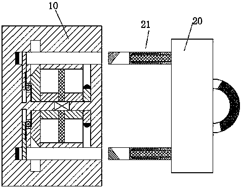
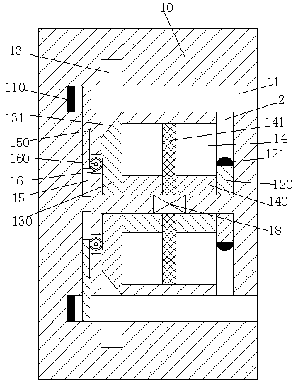
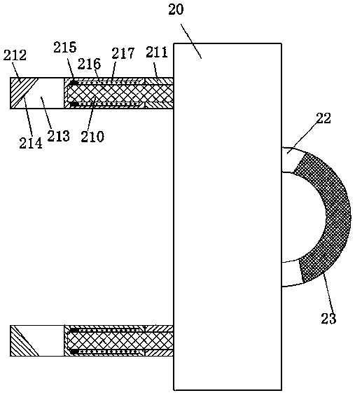
[0028] refer to Figure 1-7 , a bridge facility with high safety according to an embodiment of the present invention, including an electrical connector 10 fixedly installed in the bridge wall and an electrical connector 20 connected to electrified maintenance equipment, the upper and lower sides of the electrical connector 10 The insertion slot 11 with the...


PUM


Abstract

The invention discloses a high-safety bridge facility, which comprises an electrical connection socket fixedly arranged in a bridge wall body and an electrical connection plug connected with electrical maintenance equipment. The upper and lower portions of the electrical connection socket are symmetrically and respectively provided with an insert slot, the opening of which faces right. The upper and lower portions of the electrical connection socket are symmetrically and respectively provided with a first sliding groove, a second sliding groove and a third sliding groove, the openings of whichface to the insert slots. A communicated sliding cavity is arranged between each first sliding groove and each second sliding groove; and the sliding cavity is slidably provided with a sliding plate.Each first sliding groove is slidably provided with a sliding arm. Each second sliding groove passes through the corresponding insert slot and is slidably provided with a locking arm. The end surface, facing to the corresponding insert slot, of the locking arm is provided with a first bevel surface. The sliding plate is fixedly connected with the locking arm and the sliding arm. The end surface,facing to the insert slot, of each sliding arm is provided with an electrical contact sheet. A communicated groove is arranged between each second sliding groove and each third sliding groove. Each second sliding groove is slidably provided with a sliding bar.

Description

technical field [0001] The invention relates to the field of bridges, in particular to a bridge facility with high safety. Background technique [0002] In the infrastructure construction of bridges, many electrical connectors are preset. These electrical connectors are mainly used for plugging and power supply of electrical maintenance equipment in the later stage. However, the setting mode of these electrical connectors is too simple. When connecting, it only depends on the friction force between the electric connector and the electric connector to keep it in a motionless state, while the electrified maintenance equipment needs to move constantly during work, which makes it extremely vulnerable to dragging and pulling of the power supply line. The plugging is loose due to the impact, which leads to the interruption of power supply, which seriously affects the normal use of power supply. The sheet is easily touched by the metal sheet or metal rod. Therefore, when a person ...

Claims


Application Information

Patent Timeline
Patent Type & Authority Applications(China)
IPC IPC(8): H01R13/70H01R13/60H01R13/639H01R13/447
CPCH01R13/701H01R13/447H01R13/60H01R13/639
Inventor 潘云江
Owner 广州大正机械科技开发有限公司
Why Eureka
Try Eureka