Novel new-energy automobile device

A new energy vehicle, a new type of technology, applied in the direction of coupling devices, electric vehicles, electric vehicle charging technology, etc., can solve the problems of charging gun falling off, charging interruption, casualties, etc., and achieve the effect of increasing safety

Inactive Publication Date: 2018-06-01
广州天品科技有限公司
View PDF0 Cites 0 Cited by
  • Summary
  • Abstract
  • Description
  • Claims
  • Application Information

AI Technical Summary

Problems solved by technology

The charging pile is a supporting facility for new energy vehicles, and it is the carrier for charging new energy vehicles. However, the traditional setting mode of the charging pile is single. Accidentally touching the charging gun or being affected by the pulling of the charging cable may cause the charging gun to fall off, resulting in charging interruption. In addition, traditionally, the conductive sheet in the charging socket is generally set relatively outside. The sheet is easily touched by the metal sheet or metal rod. Therefore, when a person who lacks safety awareness inserts the metal sheet or metal rod into the charging socket, an electric shock accident is likely to occur, which is likely to cause casualties, and there is a greater safety hazard. Hidden danger

Method used


Image

  • Novel new-energy automobile device
  • Novel new-energy automobile device
  • Novel new-energy automobile device

Examples


Embodiment Construction

[0024] All features disclosed in this specification, or steps in all methods or processes disclosed, may be combined in any manner, except for mutually exclusive features and / or steps.

[0025] Any feature disclosed in this specification (including any appended claims, abstract and drawings), unless expressly stated otherwise, may be replaced by alternative features which are equivalent or serve a similar purpose. That is, unless expressly stated otherwise, each feature is one example only of a series of equivalent or similar features.

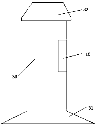
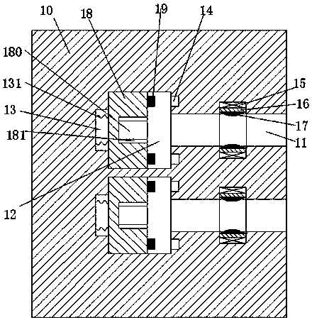
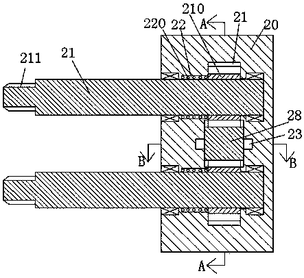
[0026] like Figure 1 to Figure 8 As shown, a new type of new energy vehicle device of the device of the present invention includes a charging pile body 30 and a charging gun 20 connected to the new energy vehicle. The charging gun 20 is provided with a sliding groove 24 with the notch facing forward, so A sliding bar 28 is slidably installed in the sliding groove 24, and the upper and lower end surfaces of the sliding bar are provided with t...


PUM


Abstract

The invention discloses a novel new-energy automobile device. The device includes a charging pile body and a charging gun connected with a new-energy automobile, a sliding groove with a groove openingfacing forwards is formed in the charging gun, a sliding strip is slidingly installed in the sliding groove, toothed strips are arranged on the upper and lower end faces of the sliding strip, rotating bins communicated with the sliding groove are symmetrically formed in the upper and lower end walls of the sliding groove, mounting holes with the openings facing leftwards run through the rotatingbins and are symmetrically formed in the upper and lower portions of the interior of the charging gun, and inserting arms are rotatably installed in the mounting holes; toothed wheels fixedly connected with the inserting arms are installed in the rotating bins, and the peripheries of the toothed gears stretch into the sliding groove to be in cooperative connection with the toothed strips; a firstannular groove is formed in the side wall of each mounting hole, one end of each torsion spring is installed in the corresponding first annular groove and fixedly installed in the first annular groove, the other end of each torsion spring is fixedly connected with the corresponding inserting arm, and an outer thread is arranged at the left end of each inserting arm.

Description

technical field [0001] The invention relates to the field of new energy vehicles, in particular to a novel new energy vehicle device. Background technique [0002] New energy vehicles are gradually replacing traditional vehicles with many advantages such as energy saving, environmental protection and pollution-free, and are widely used. The charging pile is a supporting facility for new energy vehicles, and it is the carrier for charging new energy vehicles. However, the traditional setting mode of the charging pile is single. Accidentally touching the charging gun or being affected by the pulling of the charging cable may cause the charging gun to fall off, resulting in charging interruption. In addition, traditionally, the conductive sheet in the charging socket is generally set relatively outside. The sheet is easily touched by the metal sheet or metal rod. Therefore, when a person who lacks safety awareness inserts the metal sheet or metal rod into the charging socket, ...

Claims


Application Information

Patent Timeline
Patent Type & Authority Applications(China)
IPC IPC(8): B60L11/18H01R13/66H01R13/703H01R13/629
CPCB60L53/31H01R13/629H01R13/6691H01R13/703Y02T10/70Y02T10/7072Y02T90/12
Inventor 张明
Owner 广州天品科技有限公司
Why Eureka
Try Eureka