
An optical detection device and its control method

A technology of optical detection and control method, applied in measurement devices, optical testing flaws/defects, optics, etc., can solve the problems of large occupied space and high cost of optical detection devices, and achieve the effect of reducing occupancy, facilitating defect analysis, and reducing costs

Active Publication Date: 2021-03-12
BOE TECH GRP CO LTD +1
View PDF14 Cites 0 Cited by
  • Summary
  • Abstract
  • Description
  • Claims
  • Application Information

AI Technical Summary

Problems solved by technology

[0004] Embodiments of the present invention provide an optical detection device and its control method, which can solve the problems of high cost and large space occupation of optical detection devices in the prior art

Method used


Image

  • An optical detection device and its control method
  • An optical detection device and its control method
  • An optical detection device and its control method

Examples


Embodiment Construction

[0024] Next, the technical solutions in the embodiments of the present invention will be apparent from the embodiment of the present invention, and it is clearly described, and it is understood that the described embodiments are merely embodiments of the present invention, not all of the embodiments. Based on the embodiments of the present invention, there are all other embodiments obtained without making creative labor without making creative labor premises.

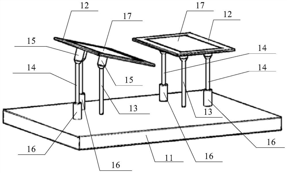
[0025] Embodiments of the present invention provide an optical detection device, such as image 3 with Figure 4 As shown, a plurality of clamping units, and a plurality of clamping units are provided on the base 11, each of which can be touched a display device to be detected, and each The clamping angle of the clamp unit can be adjusted; the image acquisition unit, the image acquisition unit, which is disposed above the clamp unit for acquiring the gradation image of the display device to detect the display device; the co...


PUM


Abstract

Embodiments of the present invention provide an optical detection device and a control method thereof, which relate to the technical field of liquid crystal display and can solve the problems of high cost and large space occupation of the optical detection device in the prior art. The optical detection device includes a base platform; a plurality of clamping units are arranged on the base platform, and each clamping unit can clamp a display device to be detected, and the clamping unit of each clamping unit The holding angle can be adjusted; the image acquisition unit, the image acquisition unit is arranged above the clamping unit, and is used to collect the grayscale image of the display device to be detected; the control unit, the control unit is connected with the image acquisition unit and multiple clamping units, The control unit is used for controlling the clamping angle of each clamping unit according to the grayscale image collected by the image capturing unit. The invention is used for testing display devices.

Description

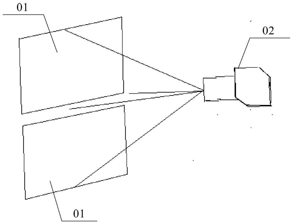
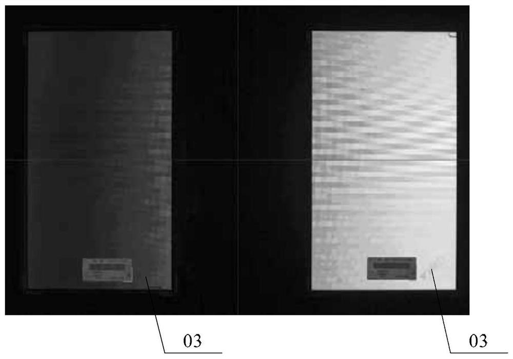
Technical field [0001] The present invention relates to the field of liquid crystal display, and more particularly to an optical detecting device and a control method thereof. Background technique [0002] During the production of the display device, the quality detection of the display screen is usually performed before the product is factory factory, and it is determined whether it meets the requirements of customer standards. The display device is used to optically detect the display device using AOI (Automated Optical Inspection, Automatic Optical Optical Detection). reference figure 1 with figure 2 As shown, in view of factors such as cost and space, the industry generally uses high-resolution CCD (Charge-Coupled Device, charge coupled device) lens 02 simultaneously optically detects the plurality of display device 01, although the existing CCD lens 02 can Autofocus, but during the actual detection, due to the center point of the CCD lens 02, the center point of the displa...

Claims


Application Information

Patent Timeline
Patent Type & Authority Patents(China)
IPC IPC(8): G02F1/13G01N21/95
CPCG01N21/95G01N2021/9513G02F1/1309
Inventor 海春喜张东升葛润聪
Owner BOE TECH GRP CO LTD
Learn More