clutch device

A clutch device and clutch technology, applied in the direction of clutches, friction clutches, mechanically driven clutches, etc., can solve problems such as short engagement-and-disengagement strokes, short axial displacement length, controllability and adjustability of clutch devices, etc.

Active Publication Date: 2021-08-17
SCHAEFFLER TECH AG & CO KG
View PDF6 Cites 0 Cited by
  • Summary
  • Abstract
  • Description
  • Claims
  • Application Information

AI Technical Summary

Problems solved by technology

Since the friction surfaces are also planar or planar, such direct-operated multi-disc clutches mostly exhibit very short engagement- and disengagement strokes, that is to say, the clutch discs press against the disc pack, or form the clutch The length of axial displacement experienced by the immediate "gap" of the plate pack is very short, which compromises the controllability and adjustability of the clutch arrangement

Method used


Image

  • clutch device
  • clutch device
  • clutch device

Examples


Embodiment Construction

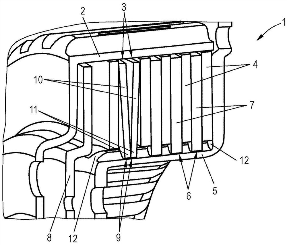
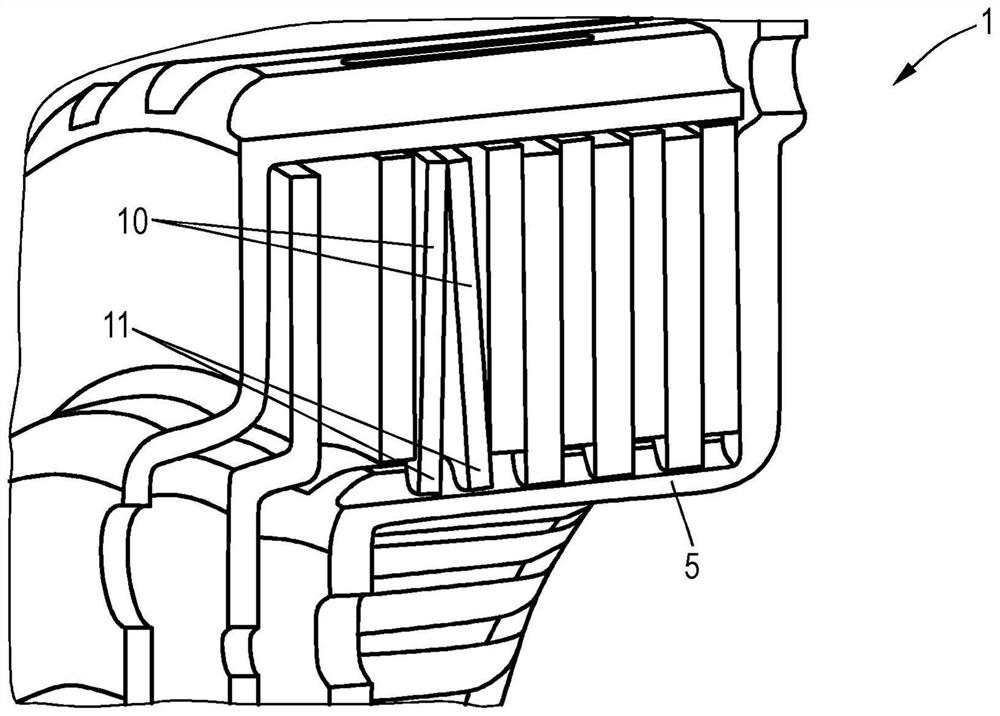
[0024] figure 1 A clutch device 1 according to the invention is shown, comprising an outer clutch plate carrier 2 with an outer clutch plate 3 arranged thereon, which in the illustrated embodiment is a friction plate 4 .

[0025] Furthermore, an inner disc carrier 5 is provided, which has an inner disc 6 , here a steel disc 7 , mounted thereon. The outer and inner clutch disks 3 , 6 form a clutch disk pack which can be compressed in the axial direction by means of an actuating element 8 , for example a pressure plate. Thus, what is involved here is a "normally disengaged" clutch arrangement in which the clutch plate pack is normally disengaged and is engaged, ie compressed, by the operating member only when required, when torque is to be transmitted.

[0026] The basic structure and function of such clutch arrangements are known and need not be described in detail.

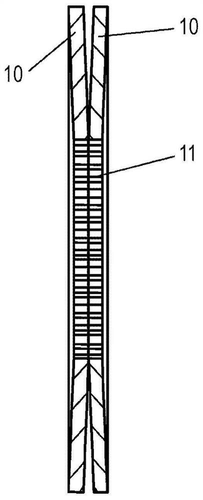
[0027] According to the invention, in the exemplary embodiment shown, the steel plate 7 is formed by two clu...


PUM


Abstract

The invention relates to a clutch device, comprising an outer clutch plate support (2) and an inner clutch plate support (5), the outer clutch plate support (2) having an outer clutch plate (3) arranged thereon, the inner clutch plate support (5) The clutch plate holder (5) has an inner clutch plate (6) arranged thereon, wherein the outer clutch plate (3) is designed as a steel plate (7) and the inner clutch plate (6) is designed as a friction plate (4 ), or design the outer clutch plate as a friction plate and the inner clutch plate as a steel plate, wherein the clutch plates (3, 6) constitute a clutch plate group that can be compressed by the operating member (8), wherein at least one The steel plate (7) is made up of two clutch discs (9) which are arranged adjacently and can be deformed to generate a restoring force when being compressed.

Description

technical field [0001] The invention relates to a clutch device, comprising an outer clutch plate support and an inner clutch plate support, the outer clutch plate support has an outer clutch plate arranged thereon, and the inner clutch plate support has an inner clutch plate arranged thereon, wherein the design The outer clutch plate is a steel plate and the inner clutch plate is a friction plate, or they are designed inversely, that is, the outer clutch plate is designed as a friction plate and the inner clutch plate is a steel plate, wherein the clutch plate forms a plate that can be pressed by the operating element. Clutch pack. Background technique [0002] Clutch devices of this type are used to connect the power output of a drive, for example an internal combustion engine, to a transmission. For this purpose, the clutch plate pack, which can be pressed by an actuating element, for example, a pressure element in the case of a "normally open" clutch or in the case of a...

Claims


Application Information

Patent Timeline
Patent Type & Authority Patents(China)
IPC IPC(8): F16D13/69F16D13/64F16D13/52
CPCF16D13/52F16D13/64F16D13/69F16D13/648
Inventor 马库斯·霍佩托斯顿·皮珀
Owner SCHAEFFLER TECH AG & CO KG
Why Eureka
Try Eureka