Rowing paddle conveniently adjusting and controlling boat speed
A technology of ship speed and transmission box, which is applied in ship propulsion, ship parts, ship construction, etc. It can solve the problems that it is difficult to control the speed of the ship and the paddle is not easy for novices to control, so that it is easy for novices to control, adjust the speed of the ship and use it conveniently Effect
- Summary
- Abstract
- Description
- Claims
- Application Information
AI Technical Summary
Problems solved by technology
Method used
Image

Examples
specific Embodiment approach 1
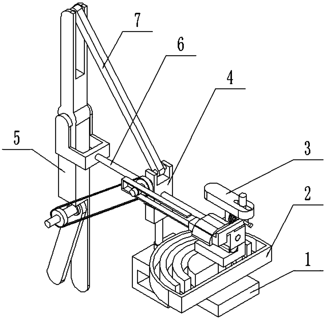
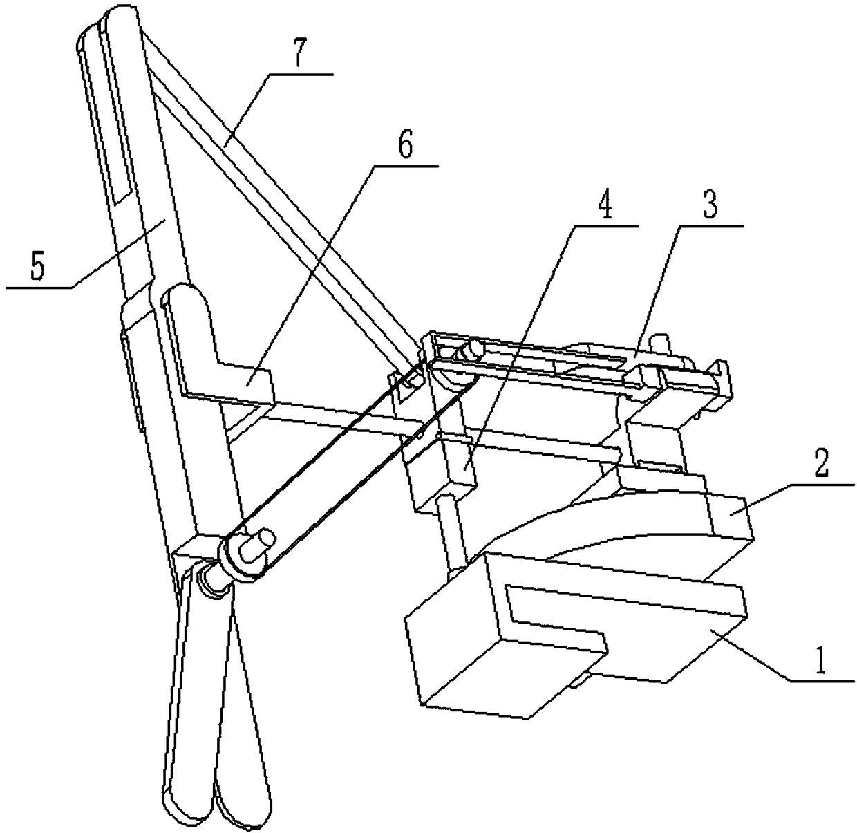
[0026] Such as Figure 1-9 As shown, a rowing oar that is convenient to regulate the speed of the boat includes a fixed seat 1, a transmission box assembly 2, a control handle assembly 3, a rotating seat assembly 4, a rowing oar assembly 5, a push-pull seat assembly 6 and a hinge plate 7. The box assembly 2 is fixedly connected to the right side of the top of the fixed seat 1; the rotating seat assembly 4 is connected to the left side of the top of the fixed seat 1 with rotation fit; The left end of the control handle assembly 3 is fixedly connected to the right end of the push-pull seat assembly 6, the push-pull seat assembly 6 is slidably connected to the upper end of the rotating seat assembly 4, and the left end of the push-pull seat assembly 6 is hingedly connected to the middle end of the rowing paddle assembly 5; The top of the rowing oar assembly 5 is hingedly connected to one end of the hinged plate 7 , and the other end of the hinged plate 7 is hingedly connected to ...
specific Embodiment approach 2
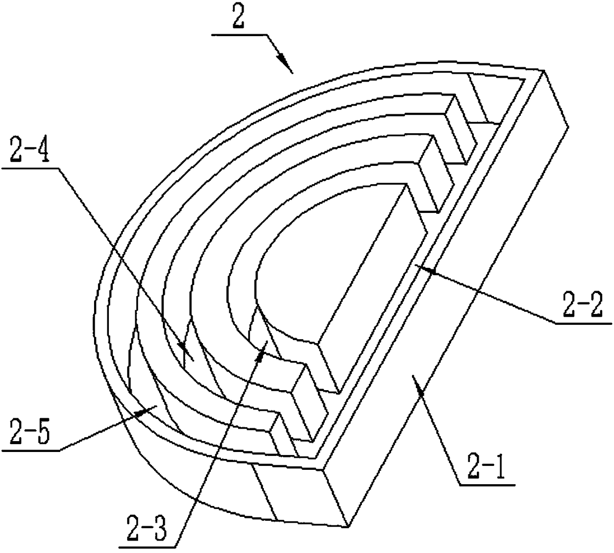
[0027] Such as Figure 1-9As shown, the transmission box assembly 2 includes a transmission box body 2-1, a rectangular push rod chute 2-2, an arc-shaped inner tie rod chute 2-3, an arc-shaped middle tie rod chute 2-4 and an arc-shaped outer tie rod Chute 2-5; the right end of the transmission box body 2-1 is provided with a rectangular push rod chute 2-2, and the left end of the transmission box body 2-1 is sequentially provided with an arc-shaped outer pull rod chute 2- 5. The arc-shaped middle tie rod chute 2-4 and the arc-shaped inner tie rod chute 2-3; the arc-shaped outer tie rod chute 2-5, the arc-shaped middle tie rod chute 2-4 and the arc-shaped inner tie rod chute 2-3 all communicate with rectangular push rod chute 2-2. When the transmission box assembly 2 is in use, the control handle assembly 3 can move forward inside the rectangular push rod chute 2-2, thereby driving the rowing paddle assembly 5 to push water backward through the push-pull seat assembly 6, and t...
specific Embodiment approach 3
[0028] Such as Figure 1-9 As shown, the control handle assembly 3 includes a handle body 3-1, a fixed column 3-2, an upper handle seat 3-3, a lower handle seat 3-4, a bump 3-5 and a control slide bar 3-6; The right side of the top of the handle body 3-1 is provided with a horizontal chute; the middle of the bottom end of the handle body 3-1 is threaded to the fixed column 3-2; the bottom end of the fixed column 3-2 is threaded to the upper the middle of the top of the handle base 3-3; the rear side of the bottom of the upper handle base 3-3 is hingedly connected to the middle of the top of the lower handle base 3-4 through a hinge shaft, and the front side of the top of the lower handle base 3-4 is fixedly connected Protrusion 3-5, the top of projection 3-5 abuts on the front side of the bottom end of upper handle base 3-3; The bottom end of described lower handle base 3-4 is connected with manipulation slide bar 3-6 by thread; The lower end of the slide bar 3-6 is slidably ...
PUM
 Abstract
Description
Claims
Application Information
 - R&D
- Intellectual Property
- Life Sciences
- Materials
- Tech Scout
- Unparalleled Data Quality
- Higher Quality Content
- 60% Fewer Hallucinations
Browse by: Latest US Patents, China's latest patents, Technical Efficacy Thesaurus, Application Domain, Technology Topic, Popular Technical Reports.
© 2025 PatSnap. All rights reserved.Legal|Privacy policy|Modern Slavery Act Transparency Statement|Sitemap|About US| Contact US: help@patsnap.com