Improved-type bridge facility

An improved, bridge-based technology, applied to contact parts, devices to prevent contact with live contacts, electrical components, etc., can solve problems such as death of personnel, low electrical connection, safety accidents, etc., and achieves convenient use, simple structure, and reduced The effect of safety hazards

Inactive Publication Date: 2018-06-22
广西南宁东能建筑工程技术有限公司
View PDF2 Cites 0 Cited by
  • Summary
  • Abstract
  • Description
  • Claims
  • Application Information

AI Technical Summary

Problems solved by technology

[0002] In the infrastructure construction of bridges, many electrical connectors are preset. These electrical connectors are mainly used for plugging and power supply of electrical maintenance equipment in the later stage. However, these electrical connectors are relatively low, and their internal conductive parts The setting is relatively outside, so that it is easy to be touched by items such as metal sheets or metal rods. Therefore, if some people who lack safety awareness use metal sheets or metal rods to insert into the electrical connector and contact the conductive parts When contacting, there will be a safety accident of electric shock, and in severe cases, it will cause death. Therefore, there is a great potential safety hazard in the traditional bridge electrical connection

Method used


Image

  • Improved-type bridge facility
  • Improved-type bridge facility
  • Improved-type bridge facility

Examples


Embodiment Construction

[0020] All features disclosed in this specification, or steps in all methods or processes disclosed, may be combined in any manner, except for mutually exclusive features and / or steps.

[0021] Any feature disclosed in this specification (including any appended claims, abstract and drawings), unless expressly stated otherwise, may be replaced by alternative features which are equivalent or serve a similar purpose. That is, unless expressly stated otherwise, each feature is one example only of a series of equivalent or similar features.

[0022] Combine below Figure 1-5 The present invention will be described in detail.

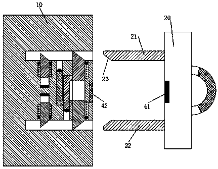
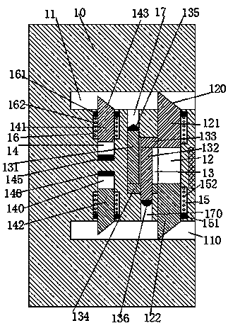
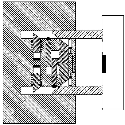
[0023] refer to Figure 1-5 , an improved bridge facility according to an embodiment of the present invention, including an electrical connector 10 fixedly installed in the bridge wall and an electrical connector 20 connected to electrical maintenance equipment, the upper and lower pairs of electrical connectors 10 etc. are provided with an upper socket 11...


PUM


Abstract

The invention discloses an improved-type bridge facility, and the facility comprises an electric connection seat which is fixedly installed in a bridge wall, and an electric connector which is connected with electrification maintenance equipment. The electric connection seat is provided with upper and lower jacks which are corresponding to each other vertically, wherein the openings of the jacks face right. Communicated sliding connection grooves are disposed between the upper and lower jacks, and the left end walls of the sliding connection grooves are provided with sliding connection cavities with the openings facing the sliding connection grooves. The top wall of each sliding connection cavity is provided with an upper through connection groove communicated with the upper jacks, and thebottom wall of each sliding connection cavity is provided with a lower through connection groove communicated with the lower jacks. The sliding connection grooves are slidingly provided with an uppersliding block and a lower sliding block, which are corresponding to each other vertically. The sliding connection cavities are slidingly provided with an upper sliding connection arm passing throughthe upper through connection groove, and a lower sliding connection arm passing through the lower through connection groove. A lower connecting rod is fixedly installed between the lower end of the upper sliding connection arm and the upper end of the lower sliding block. An upper connecting rod is fixedly installed between the upper end of the lower sliding connection arm and the lower end of theupper sliding block.

Description

technical field [0001] The bridge field of the present invention is specifically an improved bridge facility. Background technique [0002] In the infrastructure construction of bridges, many electrical connectors are preset. These electrical connectors are mainly used for plugging and power supply of electrical maintenance equipment in the later stage. However, these electrical connectors are relatively low, and their internal conductive parts The setting is relatively outside, so that it is easy to be touched by items such as metal sheets or metal rods. Therefore, if some people who lack safety awareness use metal sheets or metal rods to insert into the electrical connector and contact the conductive parts When contacting, there will be a safety accident of electric shock, and in serious cases, it will cause death. Therefore, there is a great potential safety hazard in the traditional bridge electrical connection. Contents of the invention [0003] The object of the pre...

Claims


Application Information

Patent Timeline
IPC IPC(8): H01R13/44H01R13/10H01R13/04H01R13/62
CPCH01R13/44H01R13/04H01R13/10H01R13/6205
Inventor 孙浩锋
Owner 广西南宁东能建筑工程技术有限公司
Why Eureka
Try Eureka