Valve

A valve, valve disc technology, applied to the valve. It can solve the problems of opening or closing the valve flap, which cannot be controlled, and achieve the effect of sensitive opening and closing of the valve, convenient and flexible opening.

Inactive Publication Date: 2018-06-29
苏州品幕春信息科技有限公司
View PDF0 Cites 0 Cited by
  • Summary
  • Abstract
  • Description
  • Claims
  • Application Information

AI Technical Summary

Problems solved by technology

This structure in the existing technology usually realizes the opening and closing of the valve clack manually, and the valve clack cannot be opened or closed according to actual needs, and the valve cannot be controlled by the amount of fluid flowing through the valve.

Method used


Image

  • Valve

Examples


Embodiment

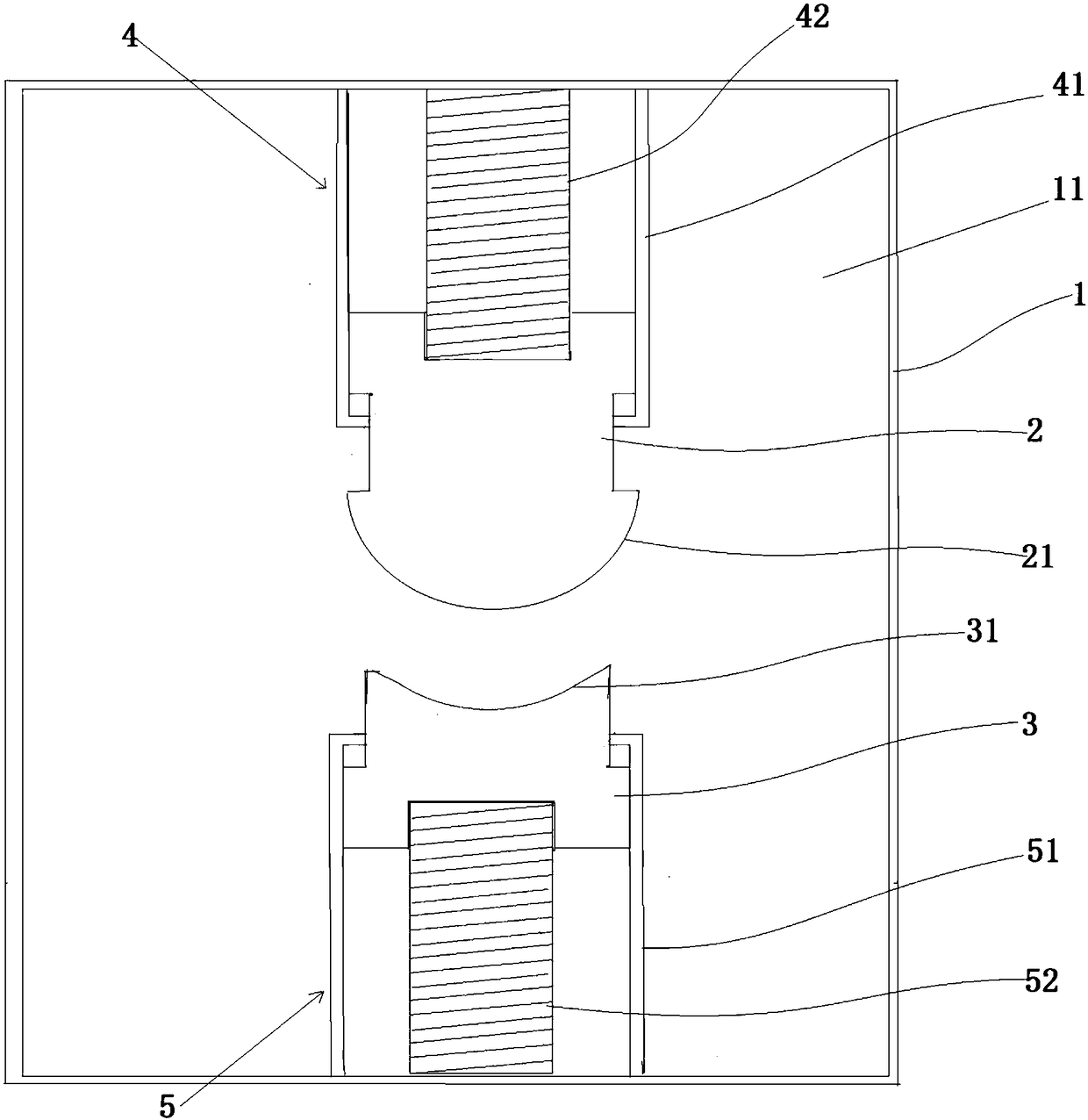
[0021] Example: such as figure 1 As shown, a valve includes a valve housing 1 , an upper valve flap 2 , a lower valve flap 3 , a first elastic member 4 , and a second elastic member 5 .

[0022] A hole 11 is arranged inside the valve housing 1 .

[0023] The upper disc 2 includes a spherical surface 21 facing downward.

[0024] The first elastic member 4 is sealingly connected between the upper valve disc 2 and the hole 11; the first elastic member 4 includes a first shell and a first spring, and the first shell is fixed to the In the channel 11 , a first mounting groove is provided inside the first housing, and the notch of the first mounting groove is downward; one end of the first spring is connected to the first mounting groove. The upper part of the upper valve flap 2 is tightly sleeved in the first installation groove, and the other end of the first spring is connected to the upper part of the upper valve flap 2 . The upper part of the upper valve flap 2 is provided w...


PUM


Abstract

The invention discloses a valve. The valve comprises a valve shell body, an upper valve clack, a lower valve clack, a first elastic part and a second elastic part, wherein the valve shell body is internally provided with a hole passage, the upper valve clack comprises a downward spherical surface, the lower valve clack comprises a spherical groove adapted to the spherical surface, the spherical surface directly faces the spherical groove, the first elastic part is connected between the upper valve clack and the hole passage in a sealed manner, and the second elastic part is connected between the lower valve clack and the hole passage in a sealed manner. The valve can be controlled according to the flow quantity.

Description

technical field [0001] The invention relates to the fields of construction pipelines, valves and the like, in particular to a valve. Background technique [0002] The basic structure of the valve is composed of valve disc, valve disc, valve cover and handle. The valve disc is installed in the cavity of the valve disc. Install the handle on one end of the disc, and use the rotation angle of the control handle to move within the range of 0 to 90 degrees to realize the opening and closing of the valve. This structure in the prior art usually realizes the opening and closing of the valve clack manually, and the valve clack cannot be opened or closed according to actual needs, and the valve cannot be controlled by the flow rate of the fluid flowing through the valve. Contents of the invention [0003] The object of the present invention is to provide a valve to solve at least one technical problem in the prior art. [0004] The technical solution to achieve the above purpose ...

Claims


Application Information

Patent Timeline
Patent Type & Authority Applications(China)
IPC IPC(8): F16K17/30
CPCF16K17/30
Inventor 陈媛媛李建
Owner 苏州品幕春信息科技有限公司
Why Eureka
Try Eureka