
Excavation positioning device and method for complex structure cavern group in geomechanics model test

A model test and complex structure technology, applied in mining equipment, earth square drilling, mining equipment, etc., can solve problems such as easy formation of joints, large errors, and large influence on test results, and achieve high positioning accuracy, easy operation, The effect of avoiding disturbance

Active Publication Date: 2019-03-29
SHANDONG UNIV
View PDF9 Cites 0 Cited by
  • Summary
  • Abstract
  • Description
  • Claims
  • Application Information

AI Technical Summary

Problems solved by technology

The disadvantage of this method is that the inner wall of the cavity is easy to form joints, and the physical and mechanical parameters between the prefabricated blocks are discontinuous, which greatly affects the test results.
In this method, some caverns are manually excavated, and the error is relatively large. Some caverns are formed by drafting, which cannot simulate the actual excavation and unloading process, and it is even more difficult to carry out excavation and positioning of caverns with complex structures.

Method used

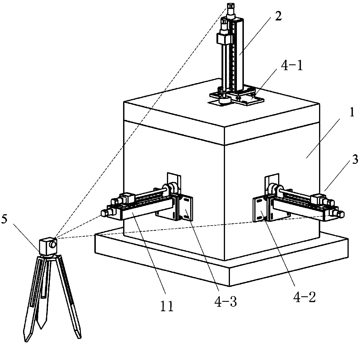
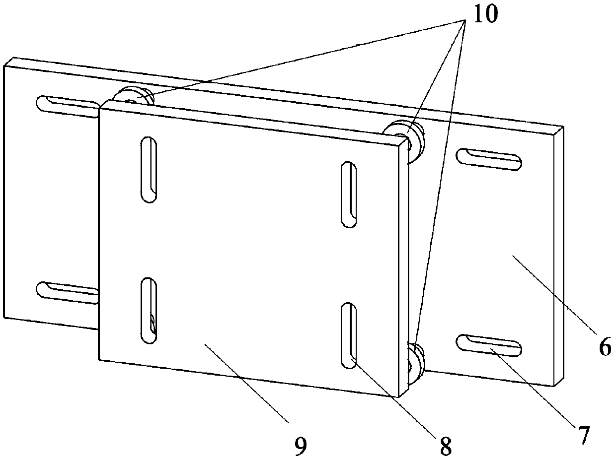
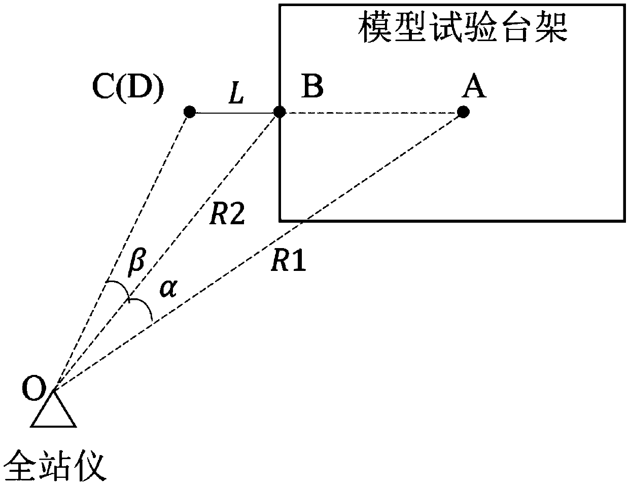

Image

  • Excavation positioning device and method for complex structure cavern group in geomechanics model test
  • Excavation positioning device and method for complex structure cavern group in geomechanics model test
  • Excavation positioning device and method for complex structure cavern group in geomechanics model test

Examples


Embodiment Construction

[0043] It should be pointed out that the following detailed description is exemplary and intended to provide further explanation to the present application. Unless defined otherwise, all technical and scientific terms used herein have the same meaning as commonly understood by one of ordinary skill in the art to which this application belongs.

[0044] It should be noted that the terminology used here is only for describing specific implementations, and is not intended to limit the exemplary implementations according to the present application. As used herein, unless the context clearly dictates otherwise, the singular is intended to include the plural, and it should also be understood that when the terms "comprising" and / or "comprising" are used in this specification, they mean There are features, steps, operations, means, components and / or combinations thereof.

[0045] As introduced in the background technology, there are deficiencies in the prior art. In order to solve th...


PUM


Abstract

The invention discloses a geomechnical model test complex structure cavern group excavating positioning device and method. The geomechnical model test complex structure cavern group excavating positioning method comprises the main steps that (1) an excavation initial point is positioned, specifically, through transverse and vertical positioning groove holes in excavation positioning plates, the position of a tool bit of an excavation device is accurately and finely adjusted, and positioning of the excavation initial point is completed; (2), the excavation orientation is positioned, specifically, through combination of a total station and software, the excavation orientation is determined, by adjusting foot screws on the excavation positioning plates, the orientation of the exaction deviceis accurately adjusted, and positioning of the excavation orientation is completed; and (3), deviation rectifying monitoring is conducted in the excavation process, specifically, after excavation positioning is completed, the position and angle of the total station are kept to be unchanged, andthe deviation of the excavation orientation is monitored in real time through a laser indicator lamp of the total station, and rectified in time. The geomechnical model test complex structure cavern group excavating positioning device and method have the following advantages that (1) the excavation positioning accuracy is high; (2) operation is easy and convenient, and disturbance to a model frame is small; and (3) the excavation orientation can be monitored in real time and rectified in time in theexcavation process.

Description

technical field [0001] The invention relates to an excavation positioning method for a model test, in particular to an excavation positioning device and method for underground engineering geomechanics model tests of complex structure caverns. Background technique [0002] With the continuous development of social productivity, the number and scale of underground engineering construction are increasing in energy, transportation, water conservancy, mining, national defense and other fields, and the development and utilization of underground space has increasingly reflected huge economic and social benefits. . At the same time, in order to meet the specific functional requirements, many underground projects are gradually going deep, and the cavern structure is gradually developing towards the multi-cavity intersecting complex structure cavern group with vertical shafts and flat caverns. Different from the traditional single or simple parallel traffic tunnels, there are obvious...

Claims


Application Information

Patent Timeline
Patent Type & Authority Patents(China)
IPC IPC(8): E21D9/14E21D9/00E21F17/18
CPCE21D9/00E21D9/004E21D9/14E21F17/18
Inventor 张强勇张岳李术才刘传成任明洋张振杰李帆苗雨生张志浩
Owner SHANDONG UNIV
Learn More