Relief valve device and high-pressure pump using same

A safety valve and valve body technology, applied in safety valves, valve devices, fuel injection devices, etc., can solve the problems of valve component lift fluctuation, pressure reduction degree fluctuation, damage to the spring, etc.

Active Publication Date: 2018-07-17
DENSO CORP
View PDF3 Cites 2 Cited by
  • Summary
  • Abstract
  • Description
  • Claims
  • Application Information

AI Technical Summary

Problems solved by technology

[0006] However, if the position of the member is adjusted by adjusting the force applied to the valve body to cope with the variation in the characteristics of the spring, the lift amount of the valve member fluctuates.

Method used


Image

  • Relief valve device and high-pressure pump using same
  • Relief valve device and high-pressure pump using same
  • Relief valve device and high-pressure pump using same

Examples


no. 1 approach

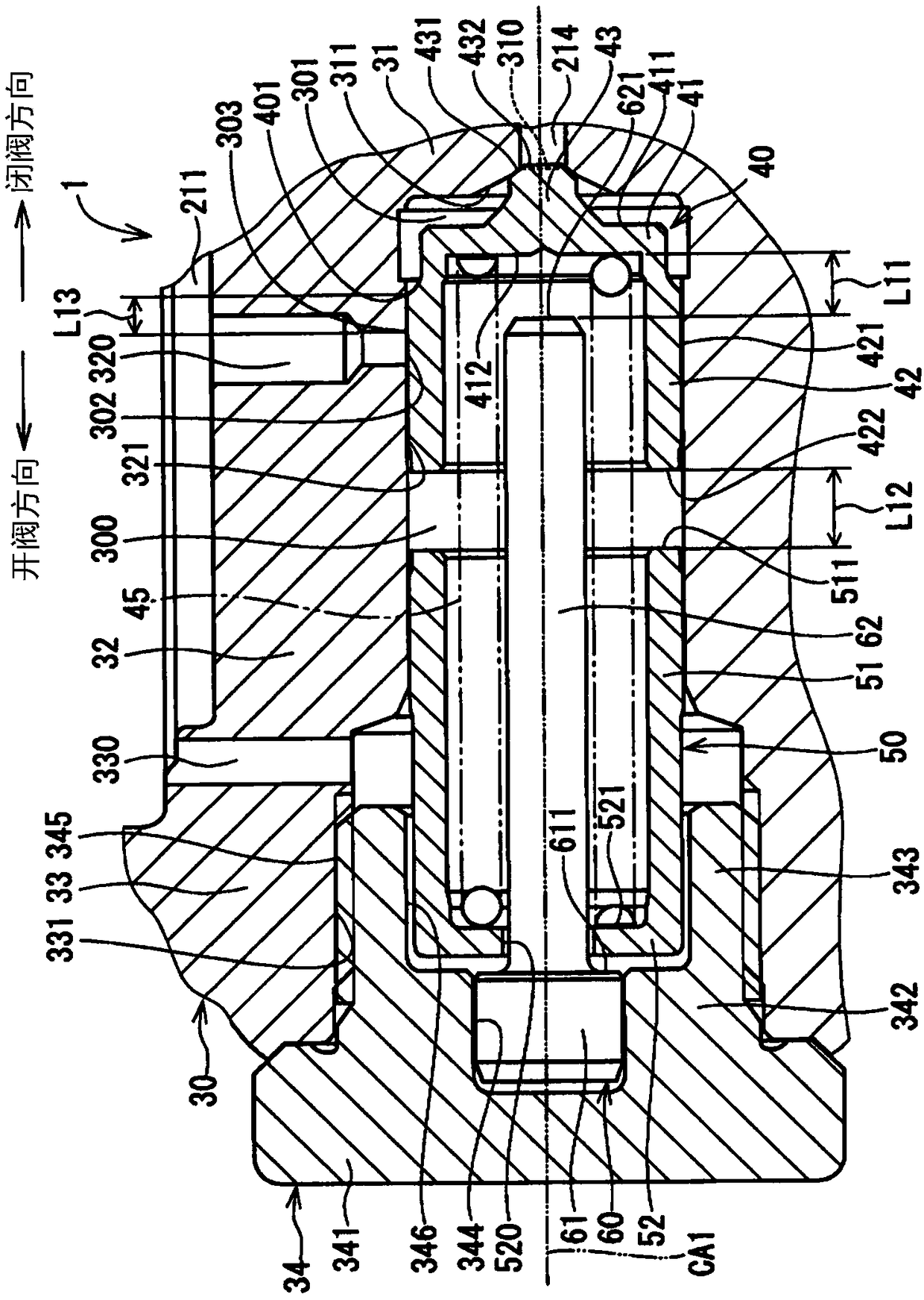
[0027] based on figure 1 , figure 2 The safety valve 1 which is the "safety valve device" which concerns on 1st Embodiment of this application is demonstrated.

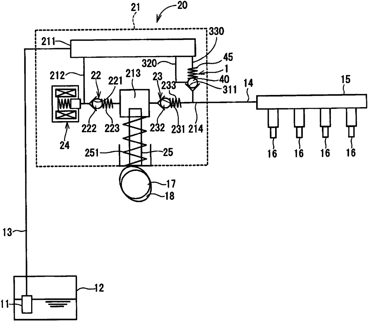
[0028] Such as figure 2 As shown, the safety valve 1 is provided on the high-pressure pump 20 . The high-pressure pump 20 is provided on a vehicle not shown. The vehicle referred to here can run, for example, using a gasoline-fueled internal combustion engine as a drive source.

[0029] The fuel pump 11 sucks fuel stored in the fuel tank 12 and supplies it to the high-pressure pump 20 through the pipe 13 . The high-pressure pump 20 pressurizes and discharges the fuel supplied from the fuel pump 11 , and supplies the fuel to the fuel rail 15 via the pipe 14 . The high-pressure fuel accumulated in the fuel rail 15 is supplied to the internal combustion engine of the vehicle via a plurality of injectors 16 connected to the fuel rail 15 .

[0030] The high-pressure pump 20 includes a pump housing 21 as a “casing”,...

no. 2 approach

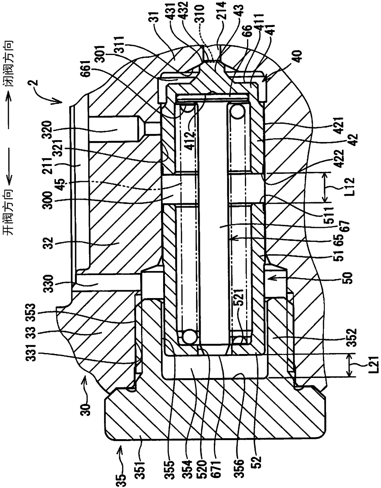
[0087] based on image 3 A safety valve device according to a second embodiment of the present application will be described. In the second embodiment, the valve housing and the stopper are different from the first embodiment.

[0088] The safety valve 2 as a "relief valve device" has a valve case 30, a valve member 40, a spring 4, a regulating pipe 50, a stopper 65 as a "restricting member", and the like. In addition, in image 3 Among them, the direction in which the inclined surface 431 of the valve member 40 moves so as to abut against the inner wall 311 of the valve housing 30 is referred to as the "valve closing direction", and the direction in which the inclined surface 431 moves so as to be separated from the inner wall 311 is referred to as the "opening direction". "Valve Direction" for illustration.

[0089] The valve housing 30 includes a valve seat portion 31 , a first cylinder portion 32 , a second cylinder portion 33 , a plug 35 serving as a “second valve body...

no. 3 approach

[0100] based on Figure 4 A safety valve device according to a third embodiment of the present application will be described. In the third embodiment, the restricting member is different from the first embodiment.

[0101] The safety valve 3 as a "relief valve device" has a valve member 40, a valve case 30 having a plug 35, a spring 45, an adjustment pipe 50, a stopper 70 as a "restricting member", and the like. In addition, in Figure 4 Among them, the direction in which the inclined surface 431 of the valve member 40 moves so as to abut against the inner wall 311 of the valve housing 30 is referred to as the "valve closing direction", and the direction in which the inclined surface 431 moves so as to be separated from the inner wall 311 is referred to as the "opening direction". "Valve Direction" for illustration.

[0102] The limiter 70 is disposed on the radially outer outer wall 421 of the sliding portion 42 . Specifically, the stopper 70 fits into the inner groove 42...


PUM


Abstract

A relief valve (1) capable of reducing the pressure of fuel in a discharge passage (214) is provided with: a valve housing (30) having a through-hole (310); a valve member (40) which is provided so asto be capable of reciprocating relative to the valve housing (30), prevents fuel from flowing between the discharge passage (214) and a fuel chamber (211) when in contact with an inner wall (311) formed around the through-hole (310), and permits fuel to flow between the discharge passage (214) and the fuel chamber (211) when moved away from the inner wall (311); a spring (45) for pressing the valve member (40) so that the valve member (40) and the inner wall (311) will be in contact with each other; an adjusting pipe (50) provided on the opposite side of the valve member (40) from the inner wall (311) and capable of adjusting the pressing force of the spring (45); and a stopper (60) provided as a separate element from the adjusting pipe (50) and coming in contact with the valve member (40) to prevent the valve member (40) from moving in the valve opening direction.

Description

[0001] Cross-reference of related applications [0002] This application is based on Japanese Patent Application No. 2015-236419 filed on December 3, 2015, and the content of the description is incorporated herein. technical field [0003] The present application relates to a safety valve device and a high-pressure pump using the safety valve. Background technique [0004] Conventionally, there is known a safety valve device that is installed so as to communicate with a first space and a second space where a fluid having a pressure lower than that of the fluid in the first space stays, and if the fluid in the first space When the pressure is above the specified pressure, the valve is opened to send the fluid in the first space to the second space, thereby reducing the pressure in the first space. For example, Patent Document 1 describes a safety valve device that includes a cylindrical valve body having a through hole communicating with the first space, is housed in the val...

Claims


Application Information

Patent Timeline
IPC IPC(8): F02M55/00F02M59/46F16K17/04
CPCF02M59/46F16K17/06F02M55/007F02M63/005F04B49/22F16K15/025F16K15/026Y10T137/7929F16K17/04
Inventor 越本振一郎小田薰泽田康弘
Owner DENSO CORP
Why Eureka
Try Eureka